Week 7 State of charge estimation
1.Simulate the 3 test cases from harness dashboard and write a detailed report on the results
BMS Model
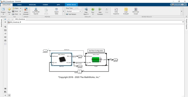
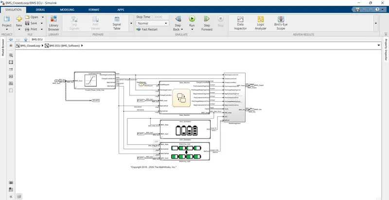
BMS ECU subsystem.
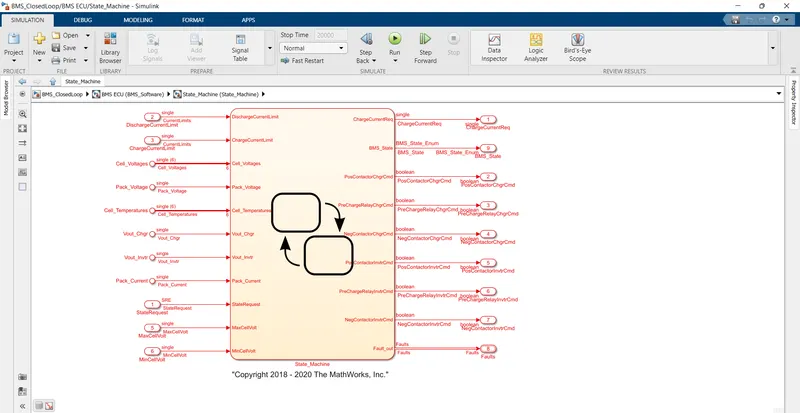
State machine subsystem
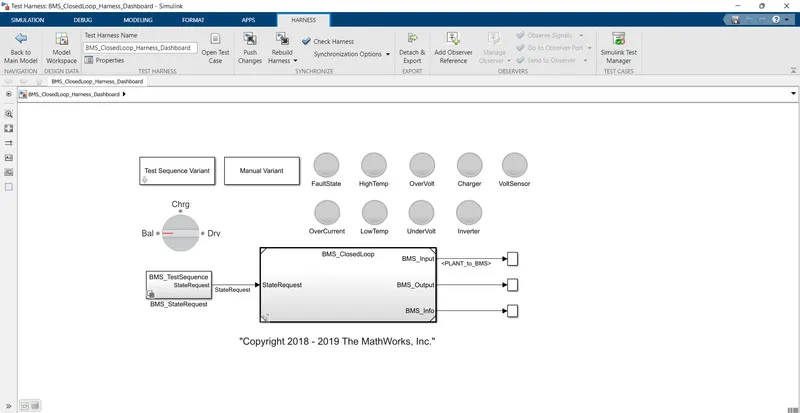
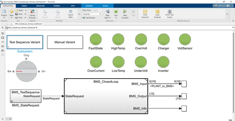
TEST HARNESS DASHBOARD
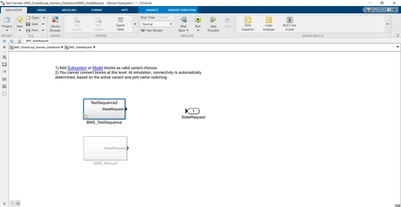
TEST CASE :1
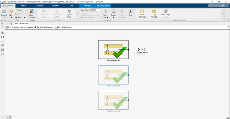
There three modes
DRIVING
CHARGING
STANDBY
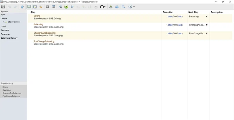
First 3000secs is driving mode and next 1000sec in balancing
And next 5000secs are for charging and 11000secs remains in standby.
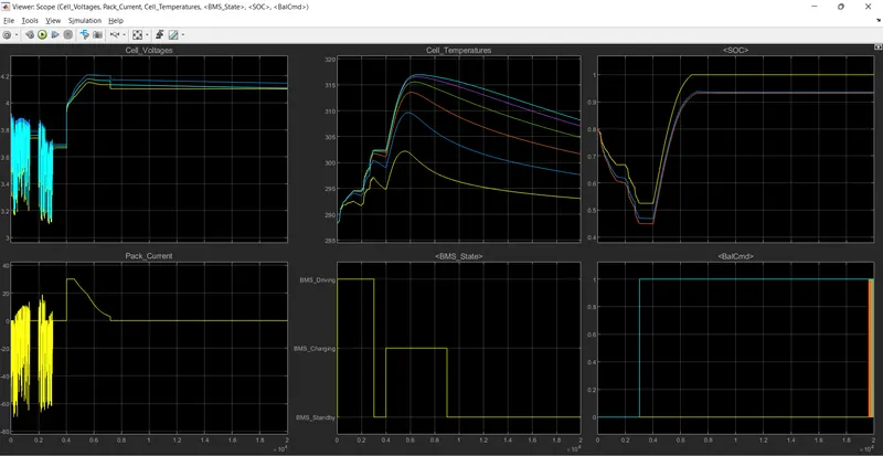
The fluctuations in the cell voltages indicates that first 3000sec indicates that the vehicle is in driving mode
And the fluctuations in pack current is also due to the driving mode.
The cell temperature increases during the driving and charging cycle and decreases when it to standby mode
The SOC Drops to 0.5 during the drive mode and increases when it is charging.
TEST CASE:2
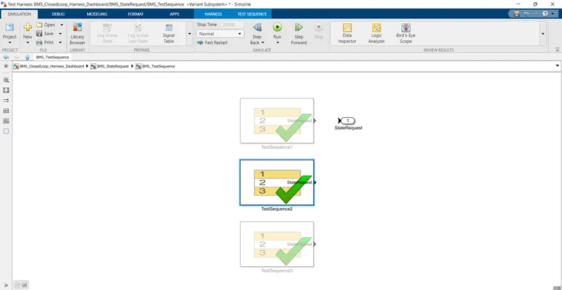
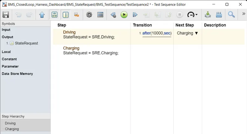
First 10000secs is in driving mode
and next 10000secs is in stand by mode
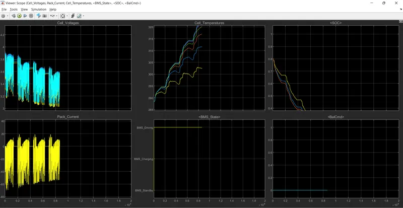
The fluctuations in the cell voltages indicates that first 10000sec indicates that the vehicle is in driving mode
And the fluctuations in pack current is also due to the driving mode.
The temperature keeps on increasing.
TEST CASE :3
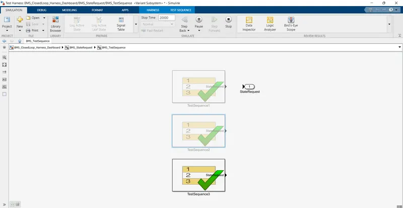
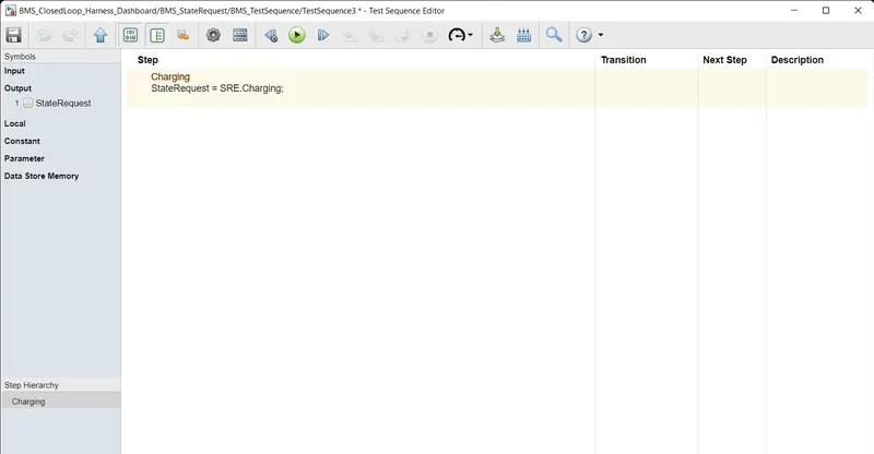
Battery is only in charging mode
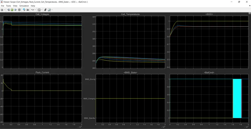
The cell voltages and pack current remains constant.
And also the temperature also remains constant and SOC is 100%
2.What is coulomb counting? Refer to the above model and explain how BMS implements coulomb counting for SOC estimation ?
Coulomb counting:
Coulomb counting is a technique used to track the state of charge of a battery pack. It works by integrating the active flowing current (measured in amps) over time to derive the total sum of energy entering or leaving the battery pack. This produces a capacity that is typically measured in amph.
In BMS ECU subsystem there is SOC estimation subsystem in that you can see coulomb counting subsystem.
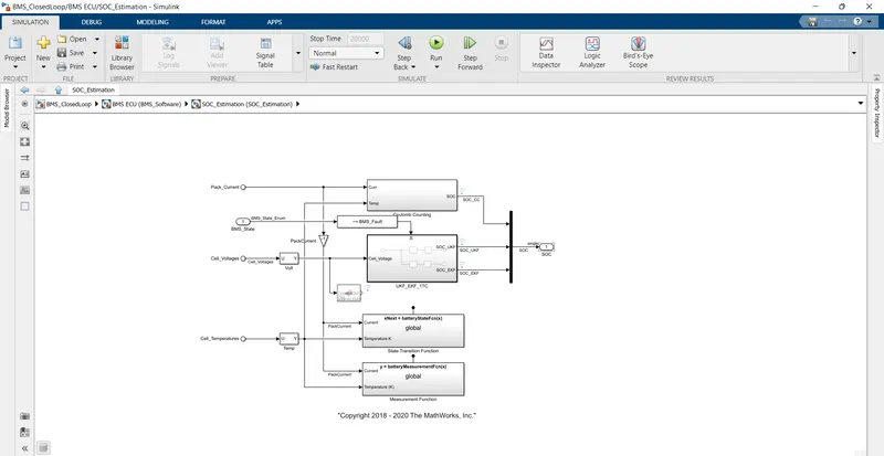
Coulomb counting estimation equation
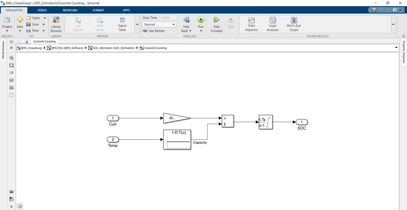
Temperature and current are the inputs to this.
Coulomb counting is simple method.
SOC is estimated.