Week - 4
AIM: Implement control logic of a washing machine using Stateflow and Make a Simulink chart for the gear shift logic.
OBJECTIVE: Control logic of a washing machine using as per given sequence
- If the power supply is available, the system gets activated
- If the Water supply is not available, stop the process & indicate through LED
- Soaking time should be 200s followed by Washing time of 100s.
- Then rinsing happens for next 20s & dryer runs for 50s.
1.Control logic of washing machine using stateflow
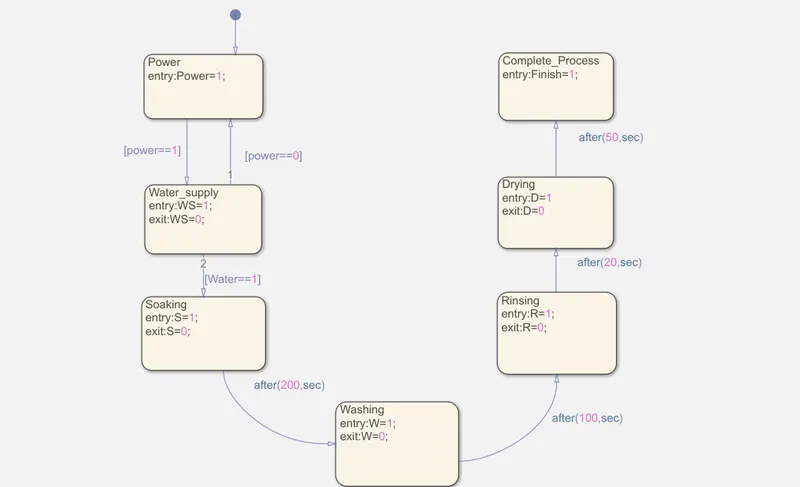
By opening simulink new model and search for chart block.
And then create the state flow of the washing machine as per given conditons
There are different steps in process of washing in washing machine they are.
- Soaking
- Washing
- Rinsing
- Drying
At first we have to give condition for power that is p=1 for on and for off p=0.
And then to the water supply same as power one is for on and zero is for no water supply.
And also same for all soaking,washing,rinising,drying and also mention the given time condtions.
When the power and water supply is in off condition.
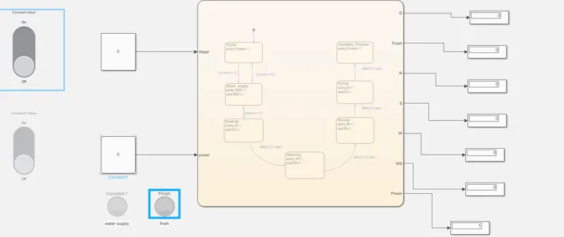
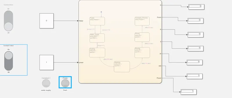
When the power is on and water supply is off.
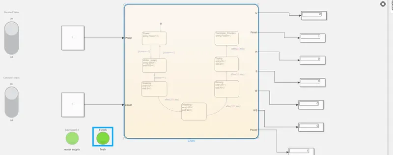
when the power and water supply is on and finished washing.
2.Simulink chart for the gear shift logic.
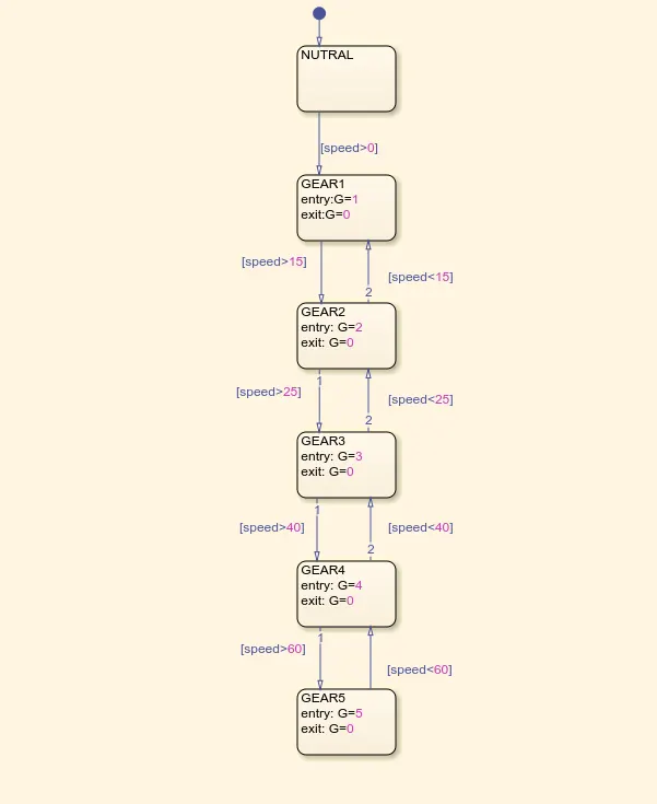
as per given conditions if speed is less than 15kmph then it should be in first gear so that condition is given as speed<15 first gear similiarly for remaing gears also the conditions are defined.
If speed is less than 25 and more than 15 it is in 2 gear.
If speed is less than 40 and more than 25 it is in 3 gear.
If speed is less than 60 and more than 40 it is in 4 gear.
If the speed is more than 60 then it is in 5 gear.
FIRST GEAR:
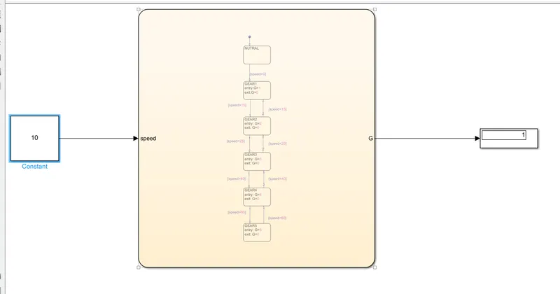
SECOND GEAR:
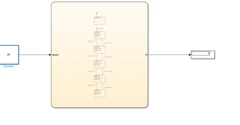
THIRD GEAR:
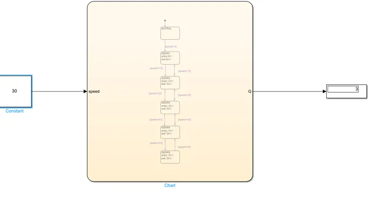
FOURTH GEAR:
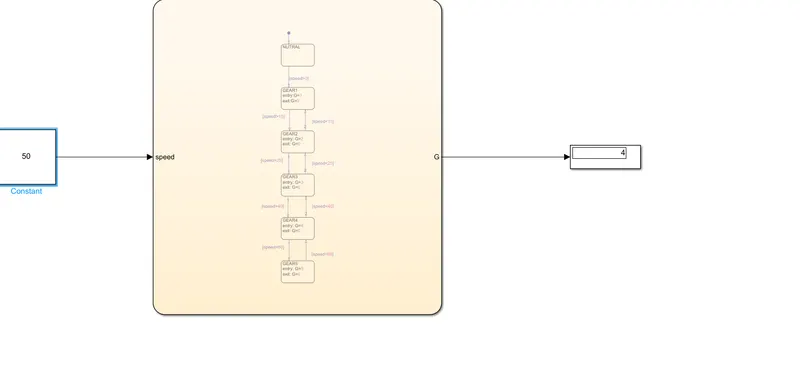
FIFTH GEAR:
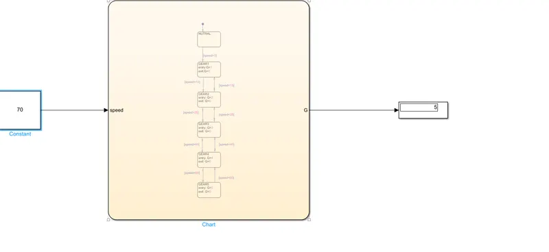
RESULT: Implement control logic of a washing machine using Stateflow as per given sequence is done and also Simulink chart for the Gear shift logic is done as given conditions.