Week 7 State of charge estimation
BMS:
A battery management system (BMS) is an electronic system that manages a rechargeable battery, such as by protecting the battery from operating outside its safe operating area, monitoring its state, calculating secondary data, reporting that data, controlling its environment, authenticating it, and/or balancing it. A battery pack built together with a battery management system with an external communication data bus is a smart battery pack. A smart battery pack must be charged by a smart battery charger.
- Simulate the 3 test cases from the harness dashboard and write a detailed report on the results

Test 1:
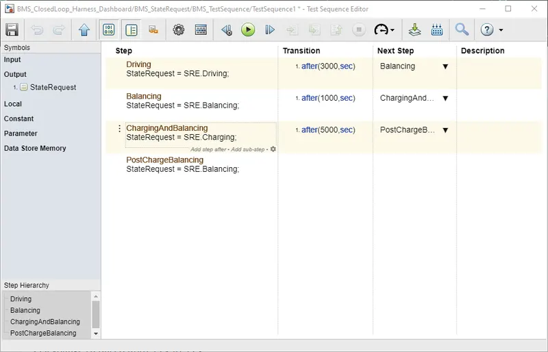
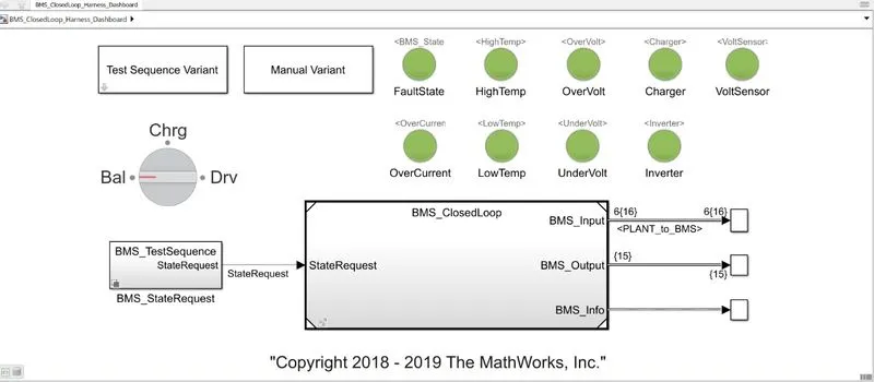
This system follows the Driving – balancing- charging- balancing sequence.
Output:
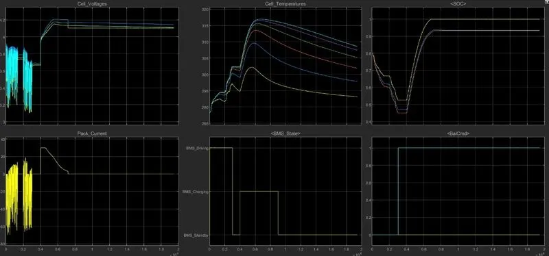
The graph shows the cell voltage, cell temperature, SOC, Pack current, BMS state, and Balancing command plots.
SOC:
The SOC decreases initially stating that the vehicle is in a driving state and continuously depleting energy and then it remains constant for a while showing that the energy is in a balanced state and then the SOC level increases and it shows that the cells are getting charged to reach the peak voltage and finally it balances again.
Cell Voltages:
In the cell voltages plot, it can be seen that the voltage rapidly fluctuates and this is due to the Driving condition and this continues till the voltage reaches 4.2 V and then it stabilizes.
Pack Current:
The pack current plot shows that the current changes frequently during the driving phase and it reaches a peak current and then it balances the current.
Cell Temperatures:
The temperatures of the cell increase during the driving and charging phase as the energy is being used in the driving state and the energy is being stored in the charging state. At the end of the charging state, the temperature reduces gradually as there is no heat generated or dissipated in the balancing state.
Test 2:
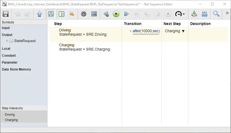
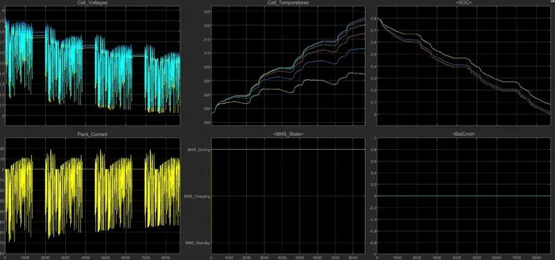
This system follows the Driving sequence.
Output:
In this sequence, the battery cell voltage fluctuates sequentially.
- The cell temperature keeps on increasing as the vehicle is in drive mode throughout the test and its heat is generated by the cell.
- The SOC graph keeps on decreasing as the vehicle is using the energy from the battery to drive.
- The pack current doesn’t stabilize as the vehicle is always driving throughout the run time and therefore the energy is used continuously.
Test 3:
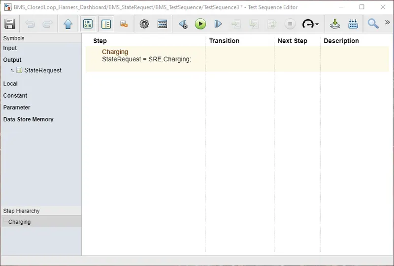
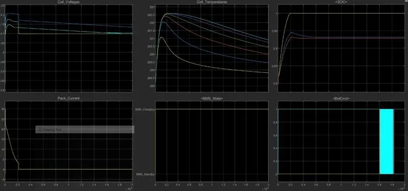
This system follows a charging-only sequence.
Output:
- This is a Charging only sequence and the cell voltage graph shows that the voltage increases and it reaches the peak voltage of 4.2 and then it gradually decreases
- The SOC plot shows that the cell is fully charged and then it is stable after attaining the complete charge. It is also noticeable that only one cell is being completely charged whereas the other cells are around 95% charged and then stabilized.
- The pack current plot initially shows the current is increased but then the pack current reaches zero and maintains at 0. It shows that the charging of the cell is completed and the BMS sends in energy in the controlled voltage format.
- The cell Temperature graph shows there is an increase in temperature and then it decreases as the charging of the cell is completed.
- What is coulomb counting? Refer to the above model and explain how BMS implements coulomb counting for SOC estimation?
Coulomb Counting:
The coulomb counting calculates the SOC by measuring the battery current and integrating it in time. Since no measurement can be perfect, it suffers from long-term drift and a lack of a reference point. The SOC must be recalibrated regularly like resetting the SoC to 100% when a charger determines that the battery is fully charged.
The Coulomb Counting method is done to estimate the SOC(t), which is estimated from the discharging current, I(t), and Previously estimated SOC values, SOC(t-1). SOC is calculated by the following equation:
`SoC (t)=SoC(t-1)+(I(t))/Q_n ∆t`
Where,
`Q_n` = Nominal capacity.
Several factors affect the accuracy of the coulomb counting method including temperature, battery history, discharge current, and cycle life.
Modified Coulomb Counting Method:
To improve the coulomb counting method, a new method is proposed. This method uses the corrected current to improve the accuracy of estimation. The corrected current is the function of discharging current. There is a quadratic relationship between the corrected current and discharging current of the battery. The corrected current is calculated as follows
`I_c (t)=k_2 I(t)^2+k_1 I(t)+k_0`
Where,
`k_0,k_1,` And `k_2` are the constant values obtained from the practical experimental data.
The system estimates the SOC by using the coulomb counting equation. This method is simple and has a low computational cost.
Coulomb counting method blocks are in the BMS Closed loop block >> BMS ECU >> SOC Estimation >> Coulomb Counting.
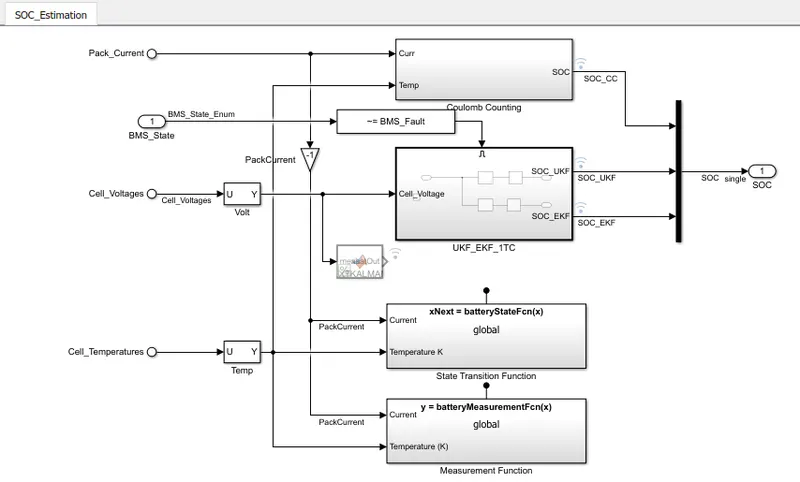
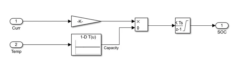
The temperature and current are taken as inputs from the cell and the battery pack respectively. The gain is divided by the capacity and it is integrated to get the SOC value.