Week 7 - Minor Project
Problem :
In this project, the student will have to set up the domain for analysis of flow over an airfoil at the subsonic and supersonic regimes. The airfoil will be analyzed at 3 different angles of attack and the lift and drag coefficient will be compared in all cases
- Create a domain for flow analysis
- Setup simulation for subsonic and supersonic regimes at
○5, 10, 15 angle of attack
Objective: For this problem, the domain and mesh developed for the previous challenge were used to run simulations. To build up the simulation, the mesh was immediately loaded into fluent.
The goal is to determine the airfoil's drag and lift coefficients for three different angles of attack: 5, 10, and 15. The simulation must be run independently for each of the three angles of attack for two flow conditions: subsonic and supersonic.
Introduction
Need for the analysis of airfoil:
Airfoil structures provide lift in airplanes, space launch vehicles, and jets, among other things. Airfoils must be analyzed not only for the lift but also for drag force, which consumes a considerable portion of the fuel energy. According to a recent study, using shark skin features that are in the fluid's flow direction can minimize drag by causing turbulence. Many developments in airfoil forms and designs have occurred in order to enhance the efficiency of the airfoil. This is achievable because of a large number of tests and simulations that have been conducted. The impact of angles of attack and delaying must be investigated in this study.
Airfoil Nomenclature
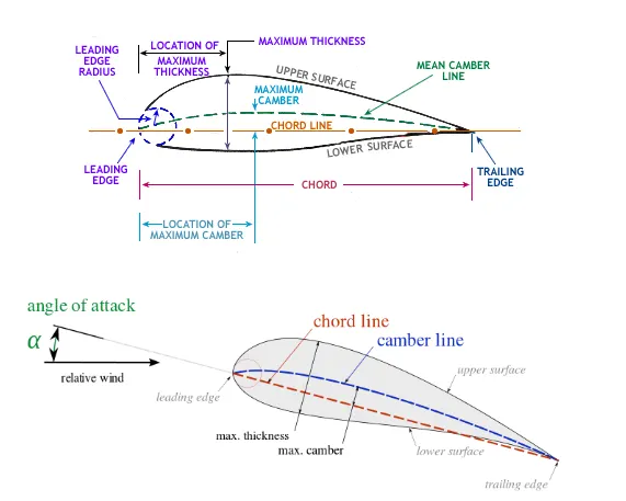
The terminology associated with aerofoils are listed below. The distance between the leading edge, which is the point at the front of the aerofoil with the most curvature, and the trailing edge, which is the point at the back of the aerofoil with the most curvature along the chord line, is defined as a chord. The leading edge is the curvature-free point at the front of the airfoil (maximum radius). The point of maximal curvature at the back of the airfoil is also known as the trailing edge. The chord line connects the leading and trailing edges and is defined as a straight line. The suction surface, which is linked with high velocity and low static pressure, is also known as the top surface. The lower surface, which has a higher static pressure, is also known as the pressure surface. The angle of attack (AOA) is the angle formed by the oncoming flow and a reference line on a body.
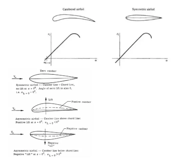
They are classed as cambered aerofoil or symmetric aerofoil based on the form of the aerofoil. As seen in Figure a symmetrical aerofoil has equal upper and lower surfaces, hence the chord line and mean camber line are the same, resulting in no life at zero AOA. These are used in the primary rotor blades of the majority of light helicopters. The chord line is placed above with a considerable curve on a cambered aerofoil, which has separate upper and lower surfaces. It is frequently included in an airfoil in order to increase the lift coefficient. The stalling speed of airplanes utilizing the airfoil is reduced as a result of this. An airplane with cambered wings will have a lower stalling speed than one with symmetric airfoil wings and the same wing loading. At zero AOA, it can also create a useful lift.
NACA Airfoil Series
The 4-digit, 5-digit, and modified 4-/5-digit NACA airfoil series were created using mathematical equations that described the camber (curvature) of the mean-line (geometric centerline) of the airfoil section as well as the thickness distribution of the section throughout its length. Later families, such as the 6-Series, include more complex forms that were created using theoretical rather than geometrical approaches. Airfoil design used to be quite random until the National Advisory Committee for Aeronautics (NACA) produced this series, with nothing to assist the designer to save previous experience with recognized shapes and experimenting with alterations to those designs.
With the publication of a NACA paper titled The Characteristics of 78 Related Airfoil Sections from Tests in the Variable Density Wind Tunnel in the early 1930s, this technique began to shift. The authors of this seminal paper noticed that the most effective airfoils have many commonalities and that the slope of the airfoil mean camber line and the thickness distribution above and below this line are the two key variables that impact those forms. They then offered a set of equations that could be utilized to build an entire family of related airfoil forms using these two variables. This fundamental technique was refined to include more variables as airfoil design got more advanced, but these two basic geometrical values remained at the heart of all NACA airfoil designs.
- NACA Four-Digit Series: The NACA Four-Digit Series was the first family of airfoils created using this method. The first digit shows the maximum camber (m) in the percentage of the chord (airfoil length), the second denotes the maximum camber position (p) in tenths of the chord, and the last two digits indicate the maximum thickness (t) of the airfoil in the percentage of the chord. For example, the NACA 2412 airfoil has a maximum thickness of 12% and a camber of 2% positioned 40 percent back from the leading edge of the airfoil (or 0.4c)
- NACA Five-Digit Series: The NACA Five-Digit Series employs the identical thickness forms as the NACA Four-Digit Series, but the mean camber line is specified differently, and the naming rules are a little more complicated. The design lift coefficient (cl) in tenths is obtained by multiplying the first digit by 3/2. When the following two figures are divided by 2, the maximum camber (p) in tenths of the chord is obtained. The last two figures show the chord's maximum thickness (t) in percentage terms. The NACA 23012, for example, has a maximum thickness of 12%, a design lift coefficient of 0.3, and a maximum camber of 15% back from the leading edge..
- Modified NACA Four- and Five-Digit Series: The airfoil sections you mention for the B-58 bomber are members of the Four-Digit Series, but the names are slightly different as these shapes have been modified. Let us consider the root section, the NACA 0003.46-64.069, as an example. The basic shape is 0003, a 3% thick airfoil with 0% camber. This shape is an asymmetrical airfoil that is identified above and below the mean camber line. The first modification we will consider is 0003-64. The first digit following the dash refers to the roundedness of the nose. A value of 6 indicates that the nose radius is the same as the original airfoil while a value of O indicates a sharp leading edge. Increasing this value specifies an increasingly more rounded nose. The second digit determines the location of maximum thickness in tenths of the chord. The default location for all four- and five-digit airfoils is 30% back from the leading edge. In this example, the location of maximum thickness has been moved back to a 40% chord. Finally, notice that the 0003.46-64.069 features two sets of digits preceded by decimals. These merely indicate slight adjustments to the maximum thickness and location thereof. Instead of being 3% thick, this airfoil is 3.46% thick. Instead of the maximum thickness being located at 40% chord, the position on this airfoil is at 40.69% chord.
- NACA 6-Series: The 6-Series' naming approach is by far the most perplexing of any of the families mentioned thus far, especially given the numerous variants. The NACA 641-212, a=0.6, is one of the more prevalent examples. In this case, the number 6 designates the series, indicating that it is intended for stronger laminar flow than the Four- and Five-Digit Series. The second value, 4, represents the chord's minimum pressure in tenths of a meter (0.4c). Low drag is maintained for lift coefficients 0.1 above and below the design lift coefficient (0.2) provided by the first number after the dash in tenths, as indicated by the subscript I. The thickness of the chord is specified by the last two numerals, which are 12 percent. The proportion of the airfoil chord across which the pressure distribution on the airfoil is uniform is defined by a=_, in this example 60 percent chord. If the amount isn't mentioned, it's presumed to be I, or the distribution is constant throughout the whole airfoil.
- NACA7-Series: The 7-Series was another attempt to enhance laminar flow areas across an airfoil by separating the places of lowest pressure on the top and lower surfaces. The NACA 747A315 is an example. The number 7 indicates the series, while the number 4 indicates the position of the minimum pressure on the top surface in tenths of the chord (40 percent), and the number 7 indicates the location of the minimum pressure on the lower surface in tenths of the chord (70 percent ). The thickness distribution and mean line shapes are shown by the fourth character, a letter. Different letters denote a succession of standardized forms drawn from prior families. The final two numerals are the airfoil thickness in the percentage of the chord, while the fifth digit denotes the design lift coefficient in tenths (0.3). (15 percent).
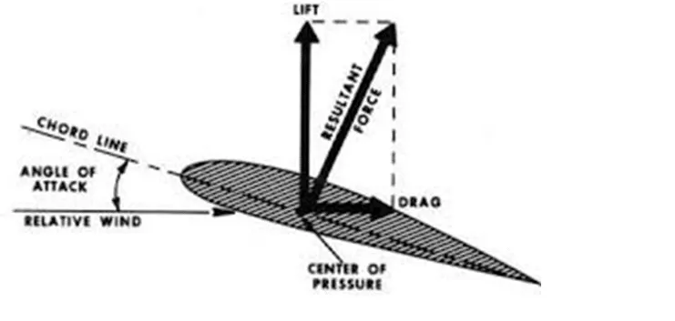
Lift theory: The airfoil is connected to the air flowing around it. As the velocity of the air comes to a halt and pressure builds up, the point at which the air first contacts the airfoil is referred to as the stagnation point. At the leading edge of the airfoil, the flow divides and attached flow occurs. The Coanda effect occurs when a flow of fluid attaches itself to a nearby surface and follows it. Bernoulli's principle states that fluid with a high velocity has low pressure and vice versa. Because the bottom section of the airfoil is concave and the top part is convex, the air flowing above will have a faster velocity than the air flowing below while the airfoil is kept in motion. This is because the convex shape lowers pressure and the concave form raises pressure ( towards the trailing edge).
Because the velocity of the particle above is always higher than the velocity of the particle below, the particles above and below the airfoil will never intersect. Because the airflow is directed downward at the trailing edge, the downward motion of air provides upward force lift, according to Newton's third law of motion or mass conservation principle. This may also be described by Bernoulli's principle, which states that there will be higher pressure below the airfoil and lower pressure above it, resulting in a net upward force lift.
Drag Theory:
The rearward force on the airfoil is known as drag. There are two forms of drag. Surface drag and pressure drag are two types of drag. When there is negative pressure at the trailing edge, it causes pressure drag, which resists forward motion. When flow separation happens early, pressure drag increases. Surface drag is connected to the body's surface. In the no-slip scenario, the velocity of the fluid layer adhering to the surface begins at zero and steadily rises away from the body until it reaches free stream velocity. The boundary layer refers to the gradient of fluid velocity surrounding the body's surface. The body was subjected to deceleration forces as a result of this.
Stalling: A stall is a situation in aerodynamics and aviation when lift begins to diminish as the angle of attack is raised beyond a particular point. The crucial angle of attack is the angle at which this happens. This angle varies greatly depending on the wing's airfoil section or profile, platform, aspect ratio, and other parameters, but most subsonic airfoils have an angle of 8 to 20 degrees relative to the incoming wind. Stalling is induced by flow separation, which begins at the trailing edge's tip and moves towards the leading edge as the angle of attack increases. At the critical angle of attack, the flow separation is large enough to cause stalling.
NACA 0012: For zero angles of attack, NACA 0012 is an asymmetric airfoil that will not provide any lift. The National Advisory Committee for Aeronautics (NACA) is an advisory body for the aviation industry. The first two digits in NACA 0012 represent the camber in the airfoil; the first digit expresses the camber in the percentage of the chord (chord length is the length of the airfoil), the second digit represents the location of the maximum camber point in tenths of a chord, and the last two digits represent the thickness in the percentage of the chord. The NACA 0012 airfoil is utilized in the following experiment.
Procedure
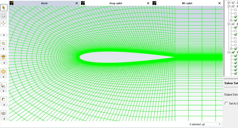
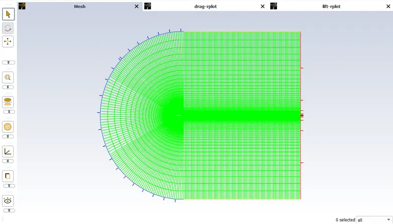
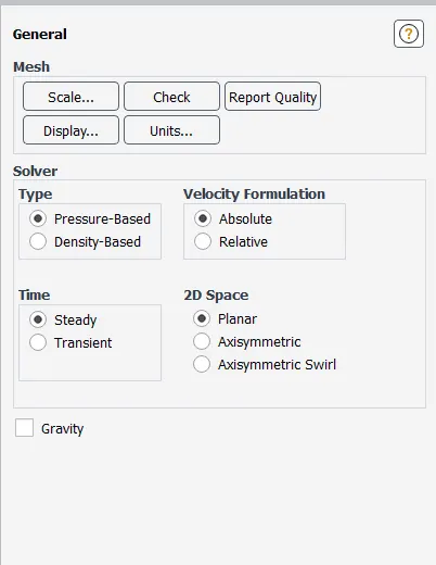
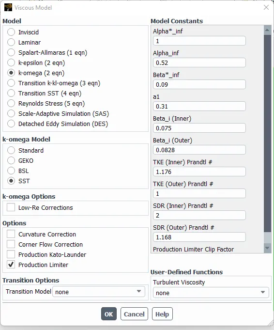
For this problem, the domain and mesh developed for the previous challenge were used to run simulations. To build up the simulation, the mesh was immediately loaded into fluent.
The goal is to determine the airfoil's drag and lift coefficients for three different angles of attack: 5, 10, and 15. The simulation must be run independently for each of the three angles of attack for two flow conditions: subsonic and supersonic.
Mesh :
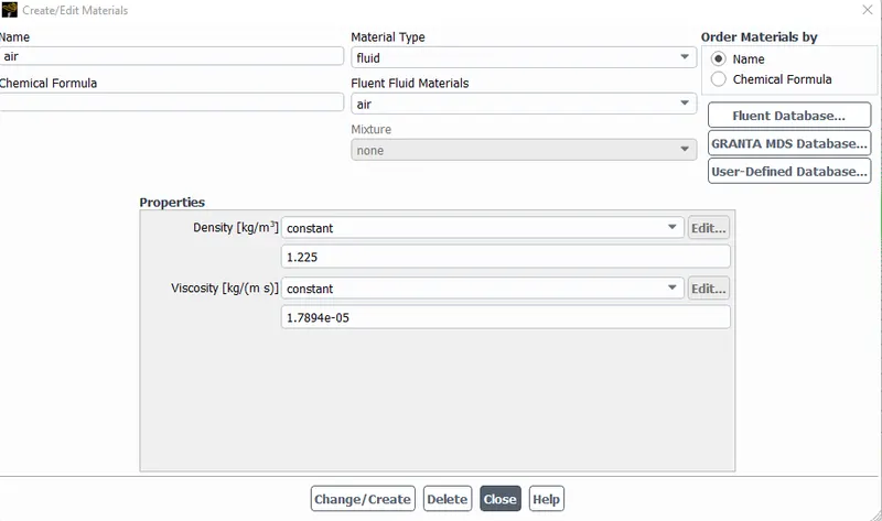
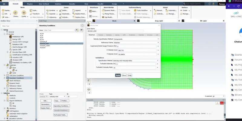
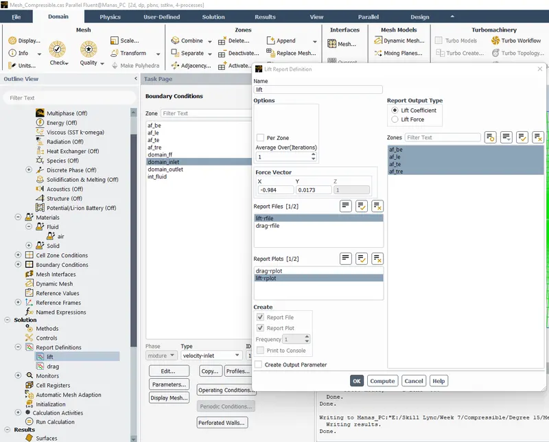
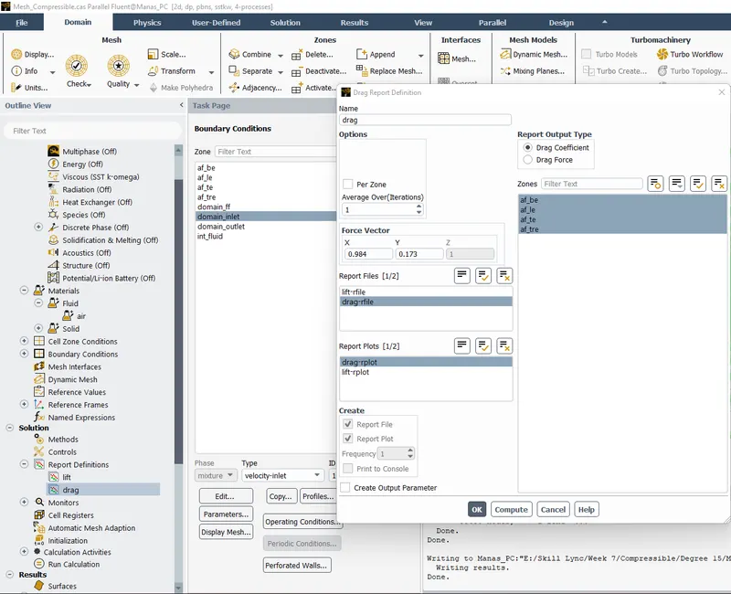
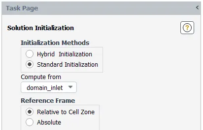
Setting up the physics :
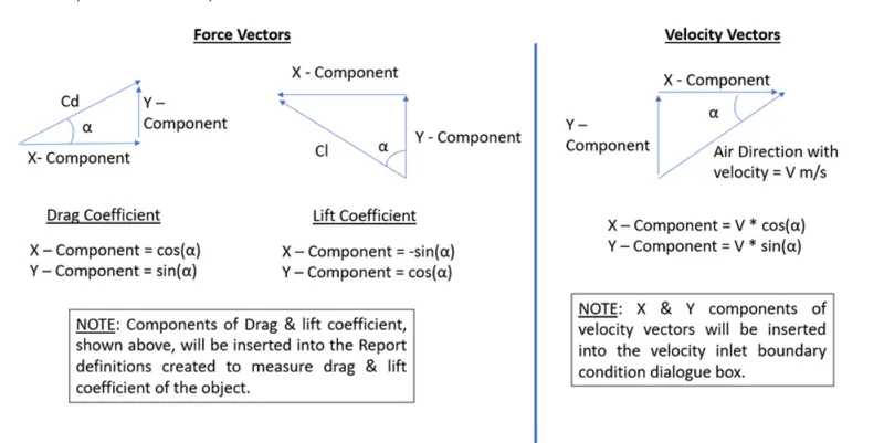
- Table for incompressible flow boundary condition
| ANGLE OF ATTACK | VELOCITY COMPONENTS | LIFT FORCE VECTORS | DRAG FORCE VECTORS | |||
| X (m/s) | Y(m/s) | X | Y | X | Y | |
| 5 | 51.802 | 4.532 | 0.996 | 0.087 | -0.996 | 0.087 |
| 10 | 51.21 | 9.02 | 0.984 | 0.1736 | -0.984 | 0.1736 |
| 15 | 50.22 | 13.45 | 0.965 | 0.258 | -0.965 | 0.258 |
- Table for compressible flow boundary condition
| ANGLE OF ATTACK | VELOCITY COMPONENTS | LIFT FORCE VECTORS | DRAG FORCE VECTORS | |||
| X (m/s) | Y(m/s) | X | Y | X | Y | |
| 5 | 270.96 | 23.706 | 0.996 | 0.087 | -0.996 | 0.087 |
| 10 | 267.86 | 47.23 | 0.984 | 0.1736 | -0.984 | 0.1736 |
| 15 | 262.73 | 70.39 | 0.965 | 0.258 | -0.965 | 0.258 |
Results :
Subsonic Flow
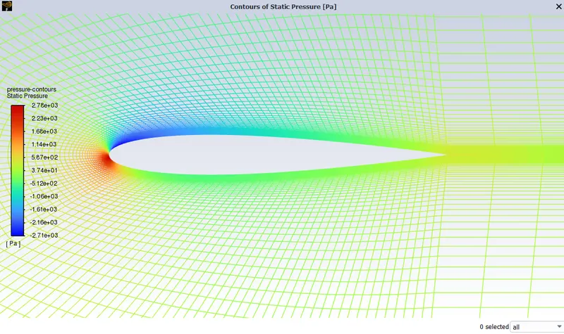
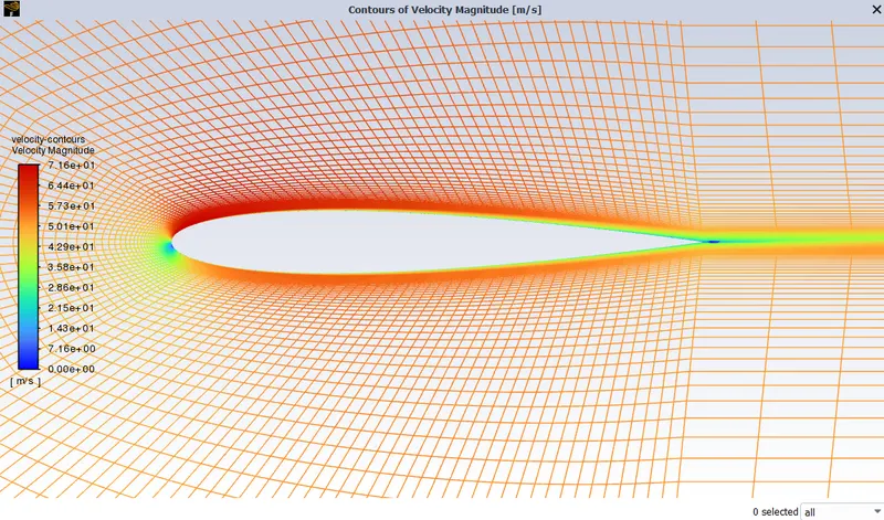
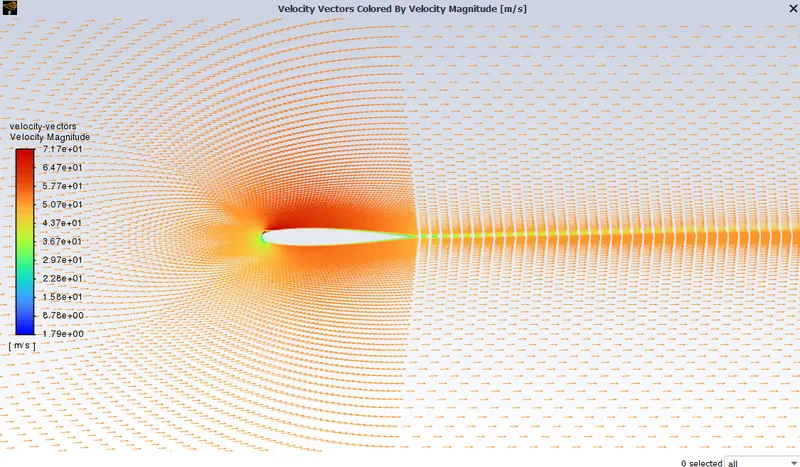
Results for the angle of attack 5 degree
Pressure Contours
Velocity Contours
Velocity Vector
Velocity Pathline
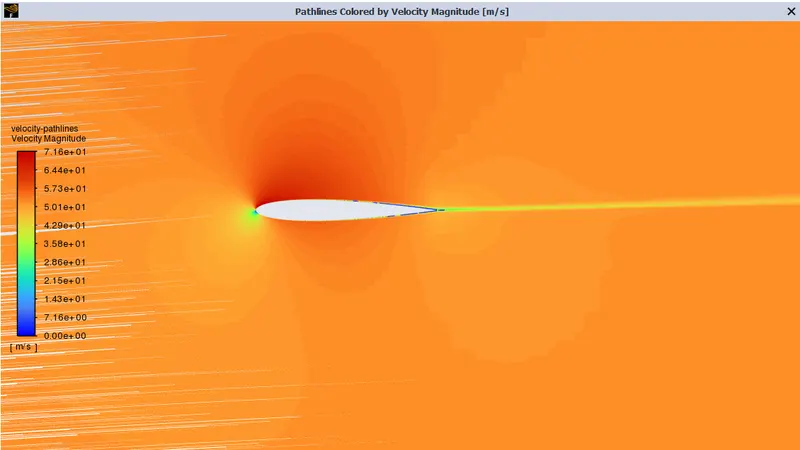
Results for the angle of attack 10 degree
Pressure Contours
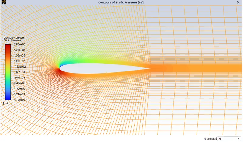
Velocity Contours
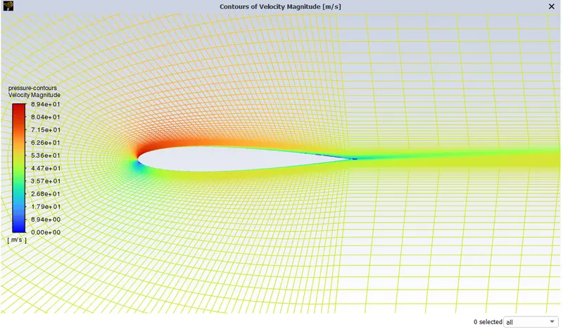
Velocity Vectors
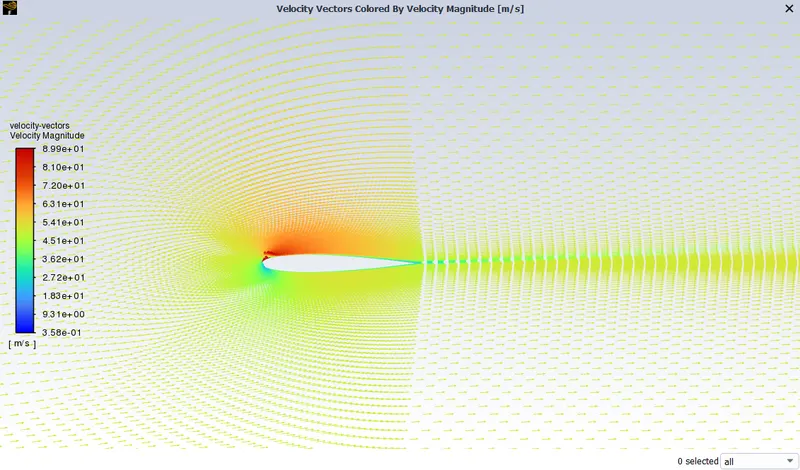
Velocity Pathline

Results for the angle of attack 15 degree
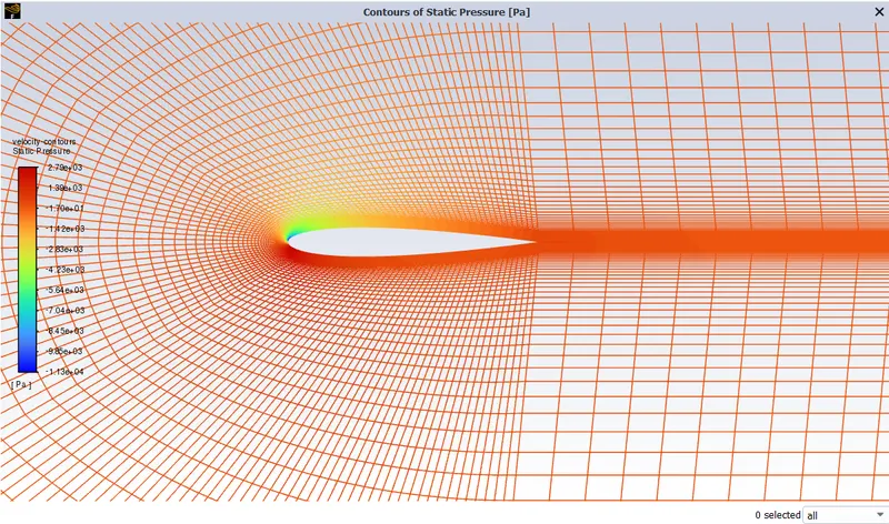
Pressure Contours
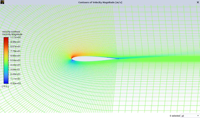
Velocity Contours
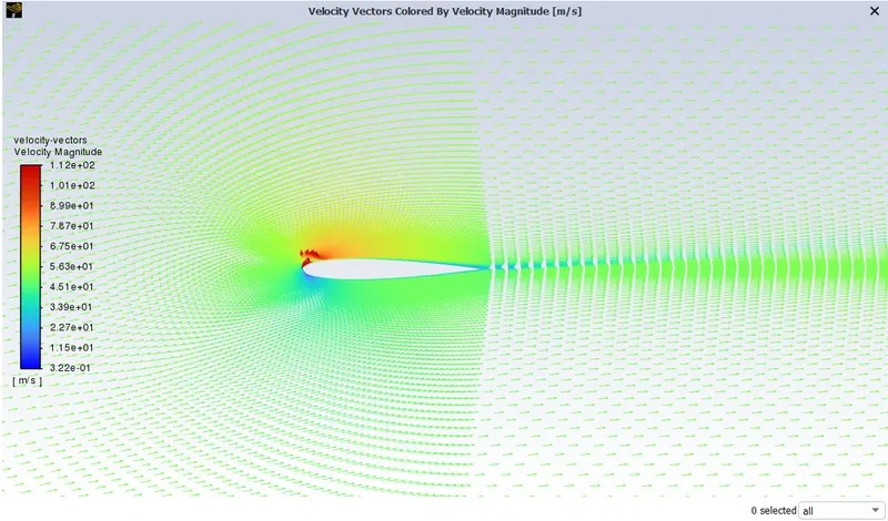
Velocity vectors
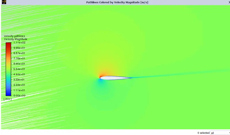
Velocity Pathline
Supersonic :
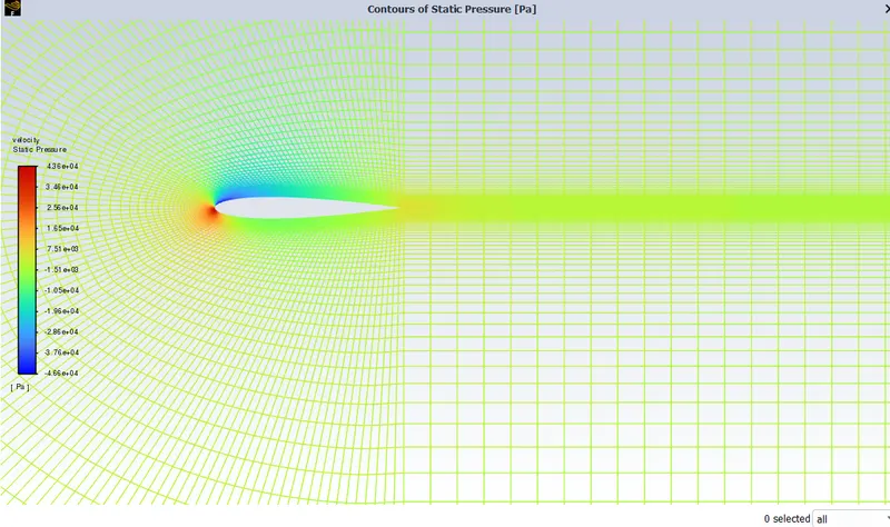
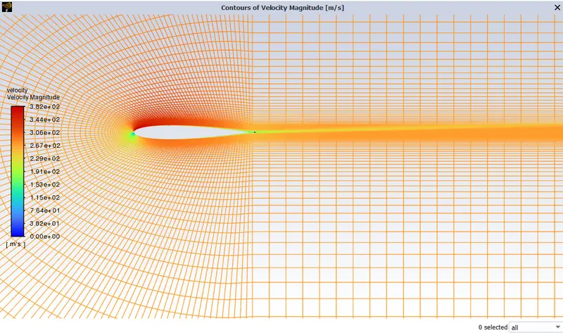
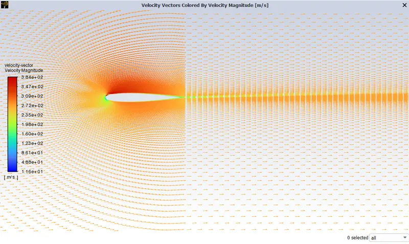
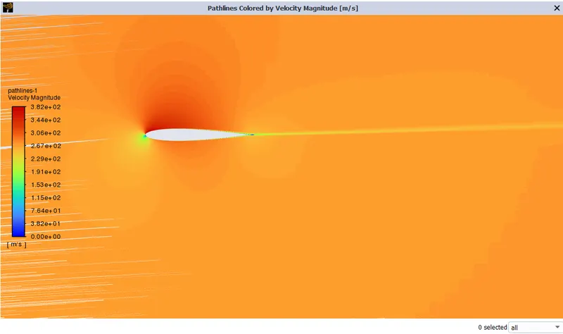
Results for the angle of attack 5 degree
Pressure Contours
Velocity Contours
Velocity Vector
Velocity Pathline
Results for the angle of attack 10 degree
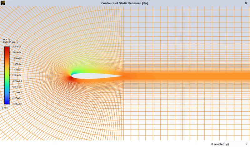
Pressure Vector :
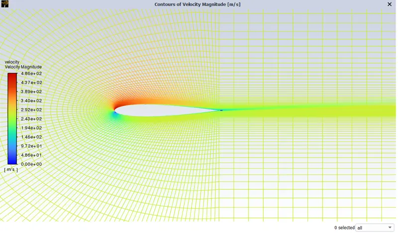
Velocity Vector :
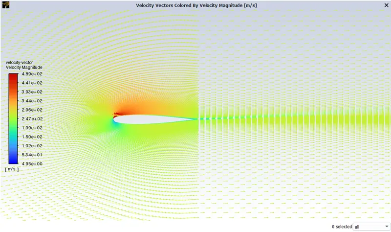
Velocity Vector
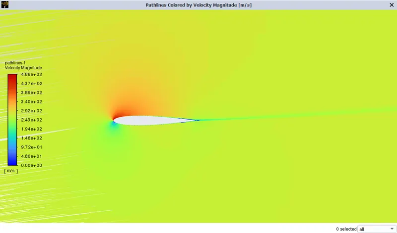
Velocity Pathline
Results for the angle of attack 15 degree
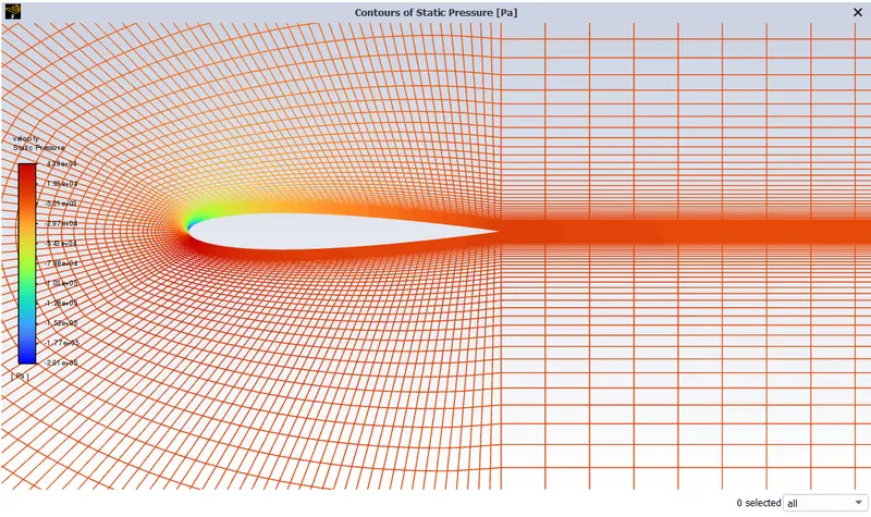
Pressure Contours
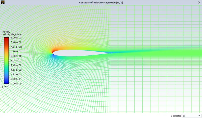
Velocity Contours
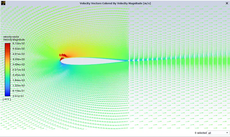
Velocity Vectors
Velocity Pathllines
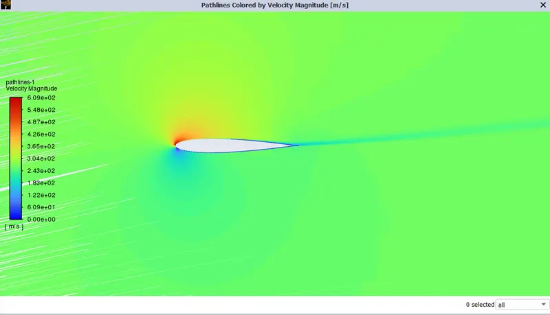
Table of coefficient of drag and lift for incompressible case
| ANGLE OF ATTACK | Cd | Cl |
| 5 | 0.020318316 | 0.029958574 |
| 10 | 0.05480157 | 0.14579032 |
| 15 | 0.10971661 | 0.33128044 |
Table of coefficient of drag and lift for compressible case
| ANGLE OF ATTACK | Cd | Cl |
| 5 | 0.019191459 | 0.036703834 |
| 10 | 0.05304934 | 0.068546501 |
| 15 | 0.1070279 | 0.37200676 |
Conclusion :
- A domain is created for flow analysis and Setup simulation is done for subsonic and supersonic regimes for 5, 10, 15 angles of attack
- From the above results, we can conclude that the coefficient of drag in the incompressible case is greater than in the compressible case. and coefficient of lift for the compressible case is greater than the incompressible case for the same angle of attack.
- The magnitude of the coefficients increases with an increase in the angle of attack