Week 7- Meshing of Backdoor Challenge
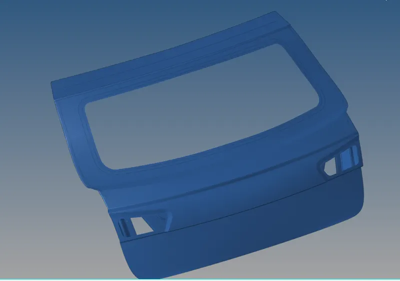
For this challenge, you will have to mesh the backdoor geometry of a car that is provided below. Provided below are the quality parameters that you have to follow.
Target Element size - 5 Units
| S.N | Quality Criteria | Value |
| 1 | Aspect Ratio | 5 |
| 2 | Skewness | 45 |
| 3 | Warping | 15 |
| 4 | Taper | 0.5 |
| 5 | Min. Length | 3 Units |
| 6 | Max. Length | 7 Units |
| 7 | Min angle Quad | 45 |
| 8 | Max angle Quad | 135 |
| 9 | Min angle Tria | 30 |
| 10 | Max angle Tria | 110 |
| 10 | Tria % | 15 |
OBJECTIVE:-
To mesh the given geometry backdoor of a car with the prescribed quality criteria which is highlighted above
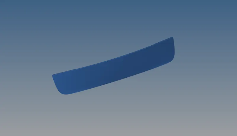
CAD MODEL IMAGE:-
PROCEDURE:-
Step 1:- Import the given geometry using import option
Step 2:-Clear the unwanted solids,points and connectors which is present in the model
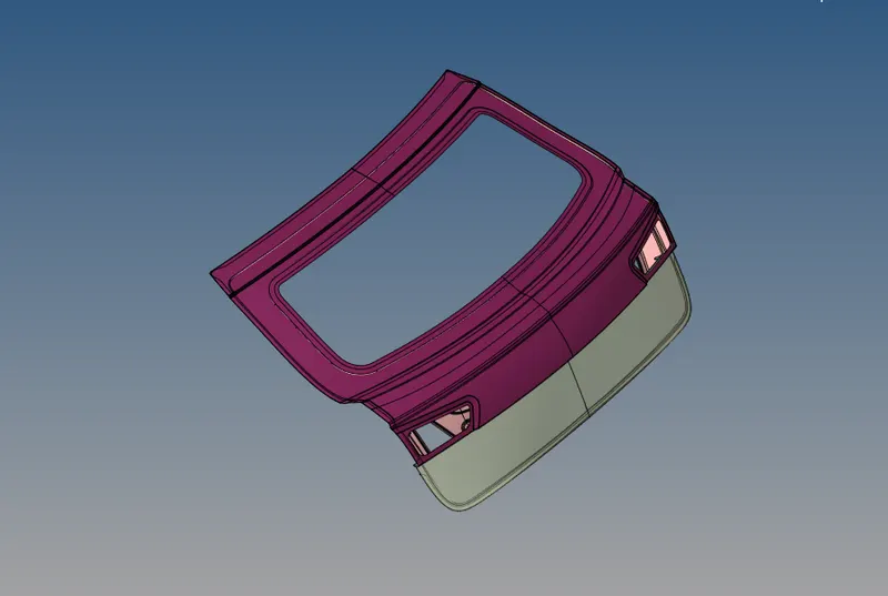
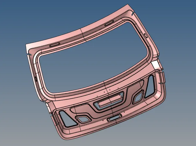
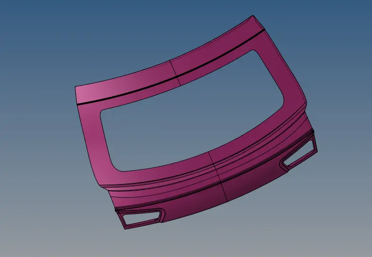
Step 3:-Split the geometry to Inner, outer and Lower using Tool->organize option (boundaries of the component need to select properly it will helps you to extract midsurface easily
->Inner
->Outer
->Lower
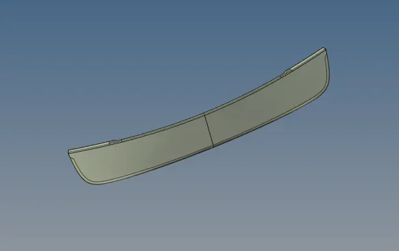
Step 4:-Extract the midsurace to the Separate components
->Inner
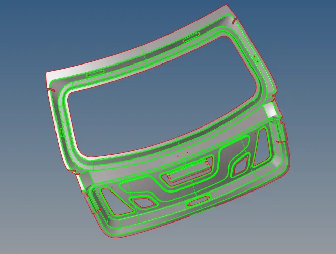
->Outer
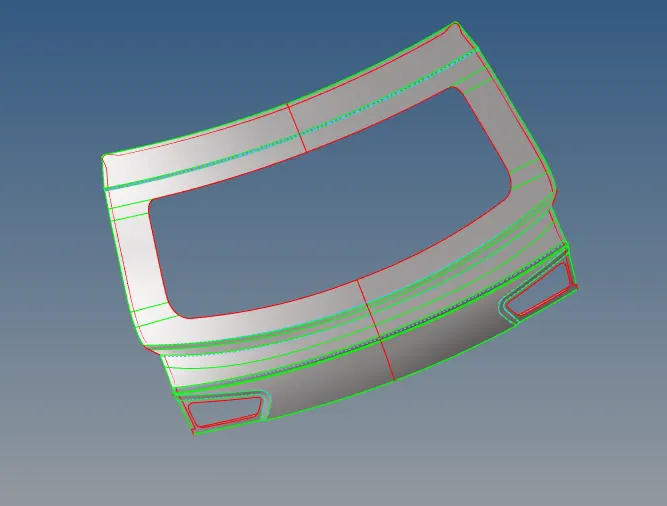
->Lower
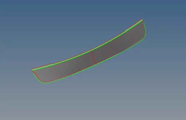
Step 5:-Enter the quality criteria which is given in question (Preferences->criteria file settings)
Step 6:-Given component we can easily found that all components are in symmetry we can delete one side of the component
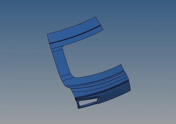
(Same procedure has been followed to other two components also)
Step 7:-Geometry cleanup need to be carried out for all surfaces uding options like toggle lines,Split surface etc., which is avaiable in quick edit option to get the proper mesh
Step 7:- Meshing need to held with the target element size of 5 units
Step 8:- To get proper mesh need to proceed with small surafces
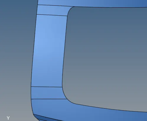
Step 9:-To get proper mesh flow re build mesh flow options helps a lot (failed areas re meshing rebuild options carried out)
Step 9:-After meshing Component need to be reflected Tool->reflect option (Before reflecting ensure the axis and Components need to be duplicated)
Step 10:- Before reflecting the component Find the free edges and ensure them to be meshed properly using appropriate command
Step 11:- After reflecting the component the areas which is joined two components need to joined using tool->edges->select all the elemenmts->preview eqivalence->equivalence
->Inner:-
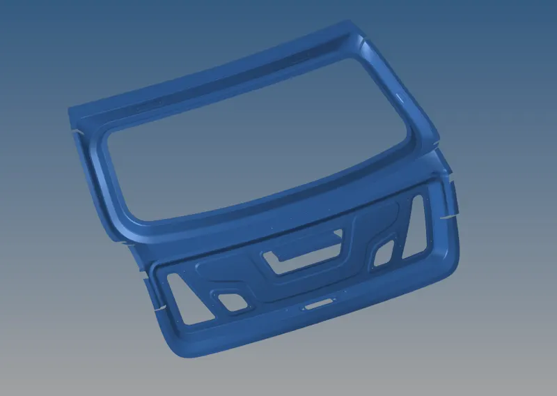
->Outer:-
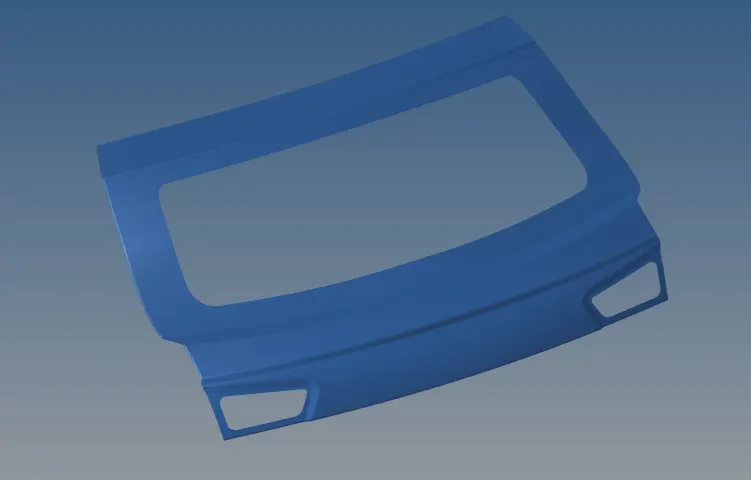
->Lower:-
Result:-
Thus the given component meshed properly with the given quality criteria and the fle has been attached below.
Final model image:-