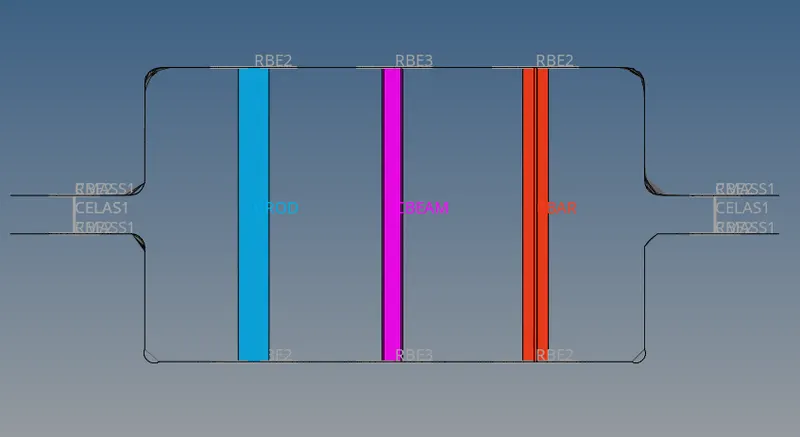
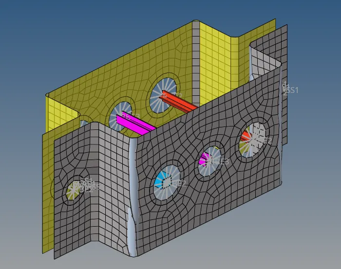
Week 4-1D Element Creation Challenge
Mesh the Given component with the Size of 5 Units. Create 1D elements on the following component with given cross-section and DOF
OBJECTIVE:-
Creating Mesh for the given component and also create 1D elements for the same component with the given cross sections and parameters
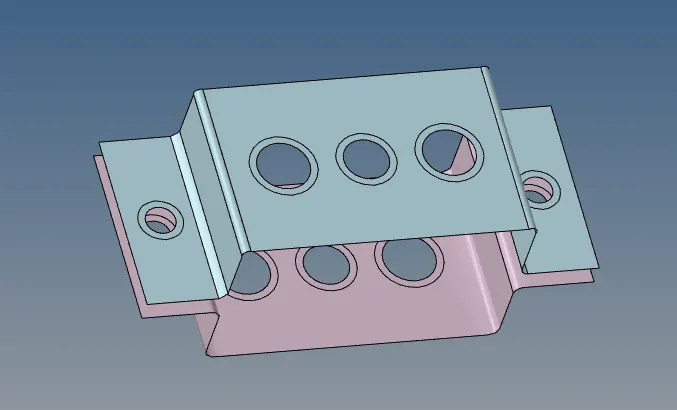
CAD MODEL IMAGE:-
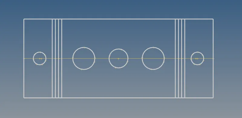
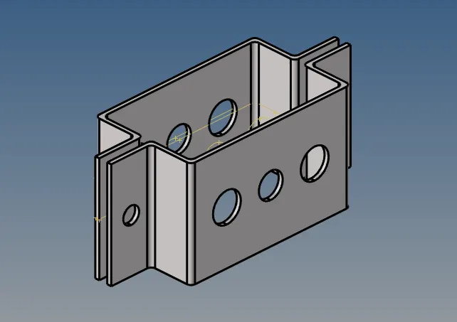
PROCEDURE:-
Step1:- Import the given IGES file using import option.
Step2:-Create Mid surafe in Bracket 1 using Mid surface option in Geometry
Geom->Midsurface->select then surf->Click Extract (Rename the component as Bracket 1)
Step3:-And create another component which is in the name of Bracket_2
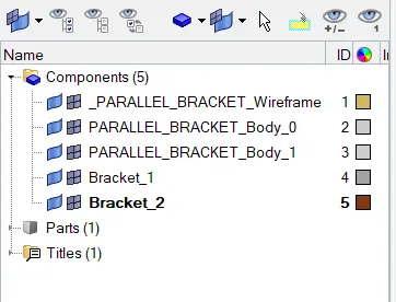
Step 4:- As in the same procedure create Mid surface for the bracket 2
Step 5:-Delete Solid present in Model using delete option Simultaneously delete the Component which is in the name of (_PARALLEL_BRACKET_Wireframe,PARALLEL_BRACKET_Body_0,PARALLEL_BRACKET_Body_1)
Step 5:- We will get another Mid surface and we have to move the to the component bracket 2 for that we need to do
Tool->organize->Select the surface which we want to move->Click move
Step 6:- Delete the Component Which is in the name of Midsurface
Step 7:-Create washer split for all the holes present in in the components to get the proper Mesh
Quick Edit-> washer split-> give the offset value (given as 5)
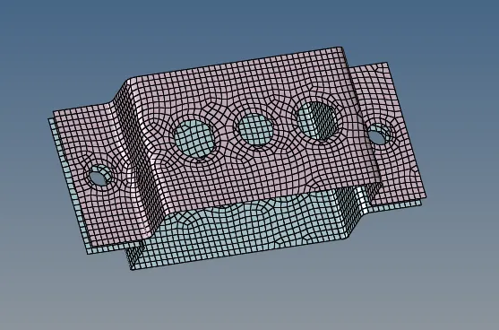
Step 8:-Mesh The Component with the element size of 5 units as per question
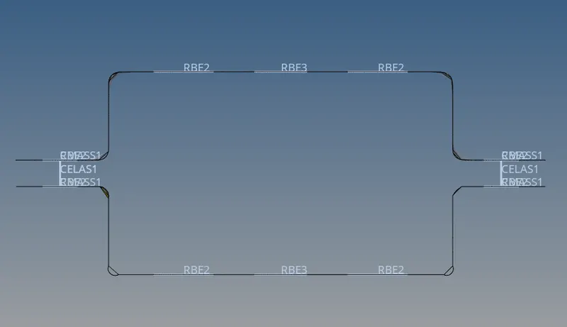
Step 9:-Create RBE2 & RBE3 links
1D->Rigids(to create RBE2 links) ->Select the node option and change to calculate node-
>Select multiple nodes -By path
Create RBE2 link for hole D & E
Step 10:- Apply the Mass to th hole D & E through 1D-> masses-> select the node and give the magnitude value as 10
Join the Components Spring elements
Step 11:- Create RBE2 link for the hole A by constraining Translational DOF (DOF 1,2& 3)
Step 12:- Create RBE3 link for the Hole B by enabling all DOF
Step 12:- Create RBE3 link for the hole C by constraining X & Y DOF (DOF 1,2,4 & 5)
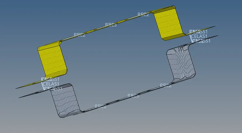
Step 13:- Select 1D-> Hyperbeam->Standard selection->Click create (it will takes you to another window)
Step14:-Enter the parameters which is in question
Step 15:- Create another I section and Cross section as per given parameters and the click model view
Step 16:- Create properties as Rod, Beam & Bar
Assign the card image as PROD,PBEAM,PBAR & Assign the Beam section Which is in the anme of BOX, I, CROSS
Step 17:-Create 1D elements of Bar,Beam & Rod using
1D->rod->Select the property as ROD -> elem type as CROD (enter the start node and End node create ROD element)
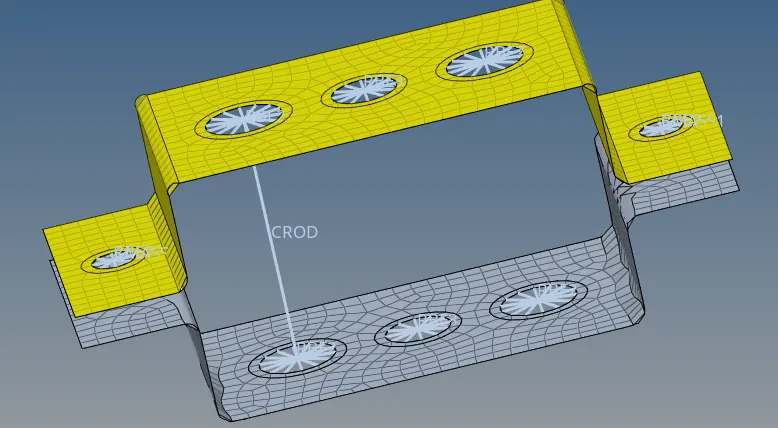
Update the property to the C rod element using update option in Rod
Step 18:- Same step 17 need to be followed to create beam and bar by giving vector direction
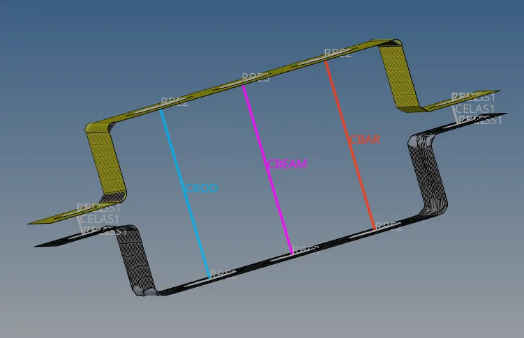
step 19:-Select 1 D detailed element representation we will get the exact result.
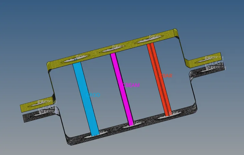
Results:-
The Given Component has been undertaken to all the given conditions and executed the conditions as per given parameters
Final Model image:-