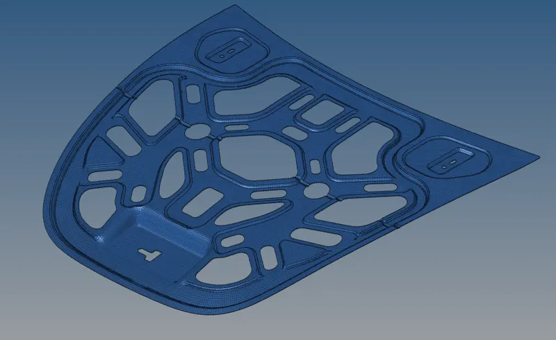
Week 6-Meshing of Hood Challenge
1)
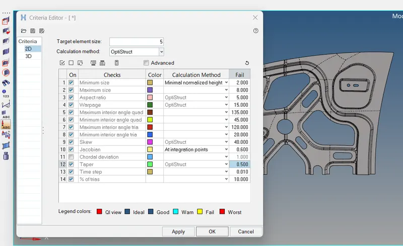
Follow the below-mentioned quality criteria, mesh the component given below and assign thickness:
Target Element Length = 5 Units
| S.N | Quality Criteria | Value |
| 1 | Aspect Ratio | 5 |
| 2 | Skewness | 45 |
| 3 | Warping | 15 |
| 4 | Taper | 0.5 |
| 5 | Min. Length | 2 Units |
| 6 | Max. Length | 8 Units |
| 7 | Min angle Quad | 45 |
| 8 | Max angle Quad | 135 |
| 9 | Min angle Tria | 20 |
| 10 | Max angle Tria | 120 |
| 10 | Tria % | 10 |
OBJECTIVE:-
To mesh the given component with the target element size of 5 units with the mentioned quality criteria
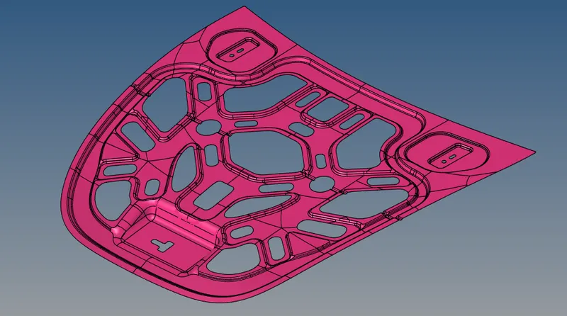
CAD MODEL IMAGE:-
PROCEDURE:-
Step 1:- Import the geometry using import option
Step 2:-Delete the unwanted solid,lines & Points which is present in the component
Step3:-Find the unsymmetric area in the component
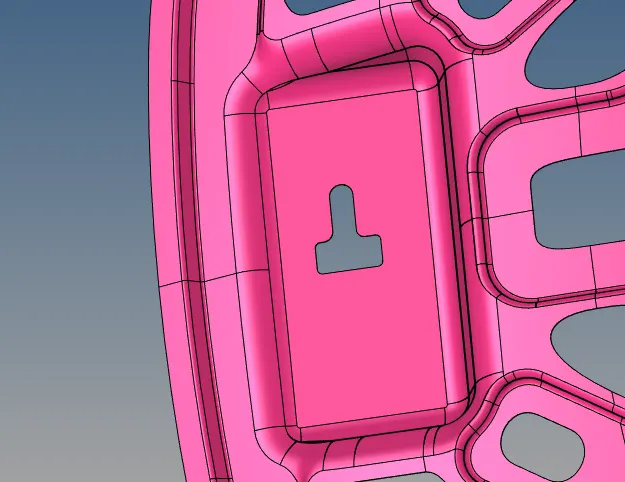
(In this component the area which is shown in the picture is in unsymmetric area)
Step4:- Create new component in the name of unsymmetric and move that particular suraface to unsymmetric component using Tool->organize->select the surface->seslect dest component as unsymmetric->Click move
Step 5:-Delete the unsymmetry surface from parent component
Step 6:- Delete the surface which is highlighted in the below picture (after finishing all the activities using reflect option we will mirror the same component)
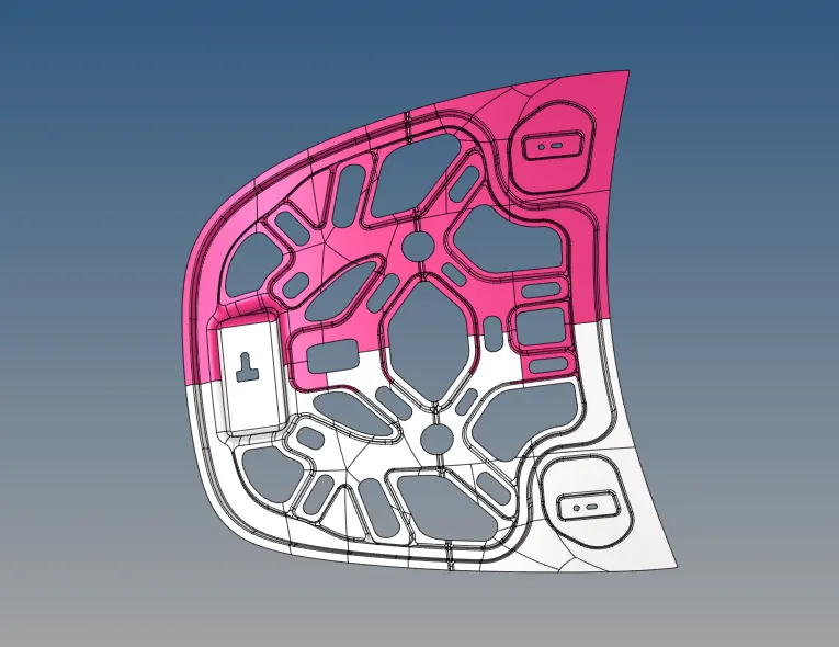
Step 6:-We will get half of the parts with some of errors (shown in picture below)
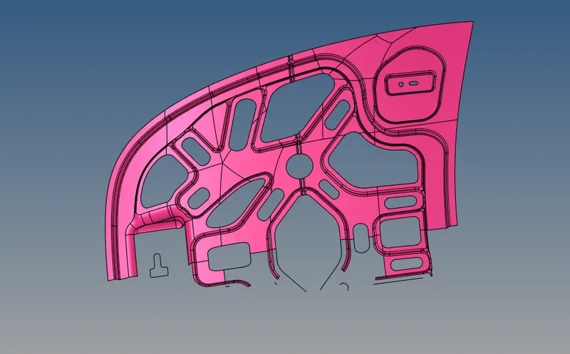
(Manually clean up those errors)
Step 7:-Do manual clean up perfectly without disturbing the Opposite surface
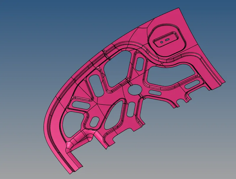
Step 8:- Create Midsurface for the component
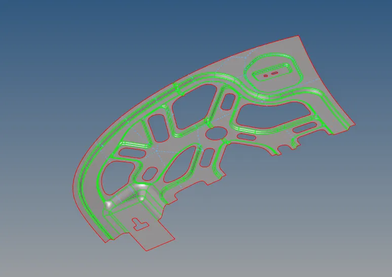
Step 9:-Toggle the lines which is available in the flat surfaces(Example shown in picture below)
BEFORE

AFTER TOGGLING
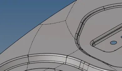
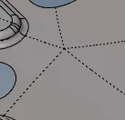
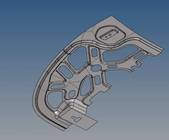
After toggling all the unwanted lines the image shown below
Step 10:-After creating mid surafaces we need to enter the quality criteria which is given in question
Preferences ->Criteria file settings-enter the values-Click apply->OK
Step 11:-Next step is to create auto mesh with the tareget unit size of 5 with mixed mesh type
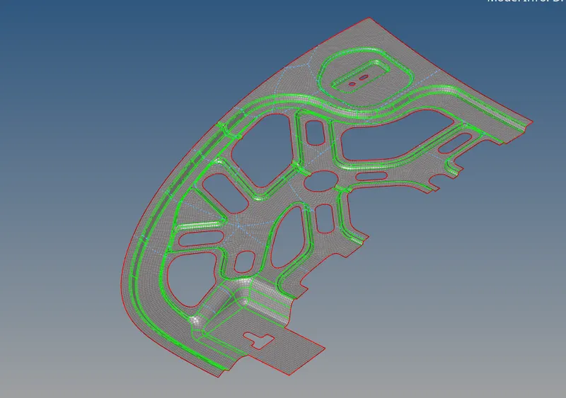
Step 12:-After meshing fine meshing need to ensure using rebuild mesh option or remeshing the particular elements
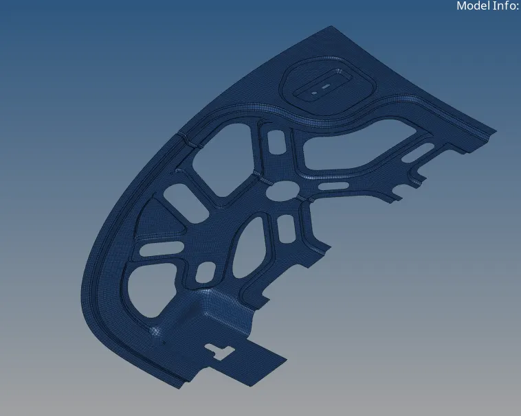
Note:- Meshing need to meet quality requirements
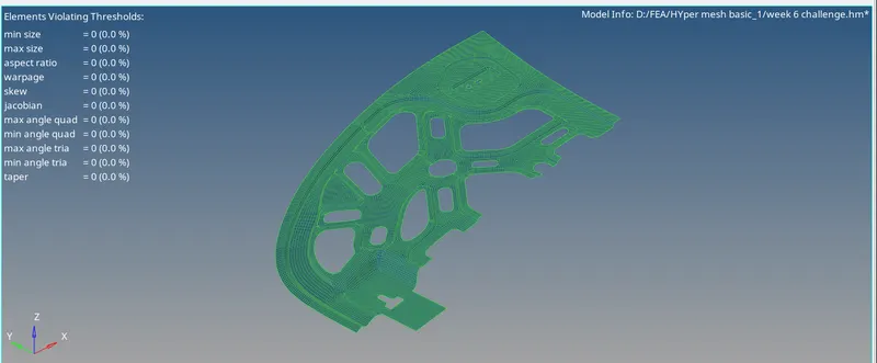
Step 13:-After finishing meshing we need to reflect the component to the opposite side
For that Go to Tool-> reflect->Select all the elements -> (change to Y axis due to component lies in y axis)-enter the base node->Click reflect
NOTE:-Before reflecting all elements unselect the unsymmetry coomponent (If Unsymmetry component refelected we will get ununiform elements) simultaneously duplicate the all the elements to get the full component
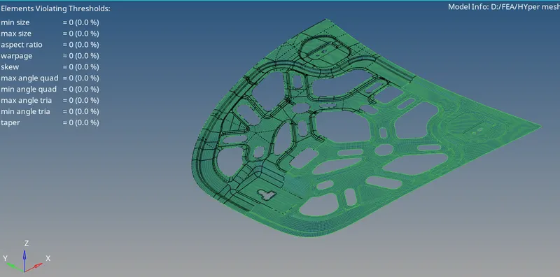
Step 14:- After reflection we need to toggle Symmetry lines using Tool -> Edges -> preview eqivalence -> Eqivalence (Give the tolerance value less than our min element size)
(Again if we get free edges in the component manual we need to clear using replace or rebuild mesh or auto meshing particular elements
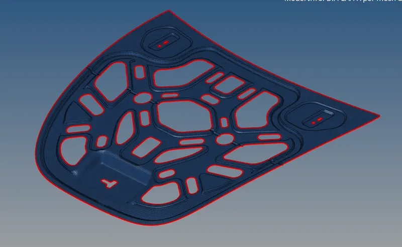
Free edges inside the component cleared
Step 15:-Next step is to assign the thickness to the component for that we need to create property and enter the thickness (here we can take its as 2 mm)
Step 16:-Assign the particular property in the component
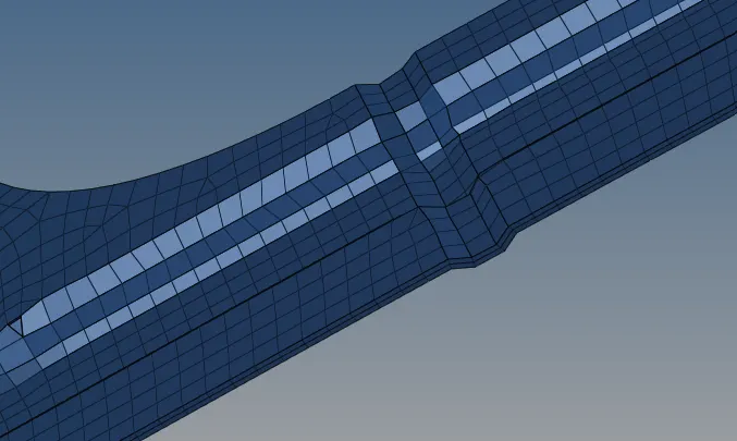
Manually check the componet using 2D traditional detailed representation
RESULT:-
Thus the given component is meshed with the given quality criteria without any defects
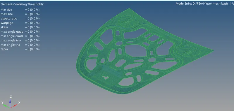
FINAL MODEL IMAGE:-