Week 7-Long Piston With Cam
Aim-
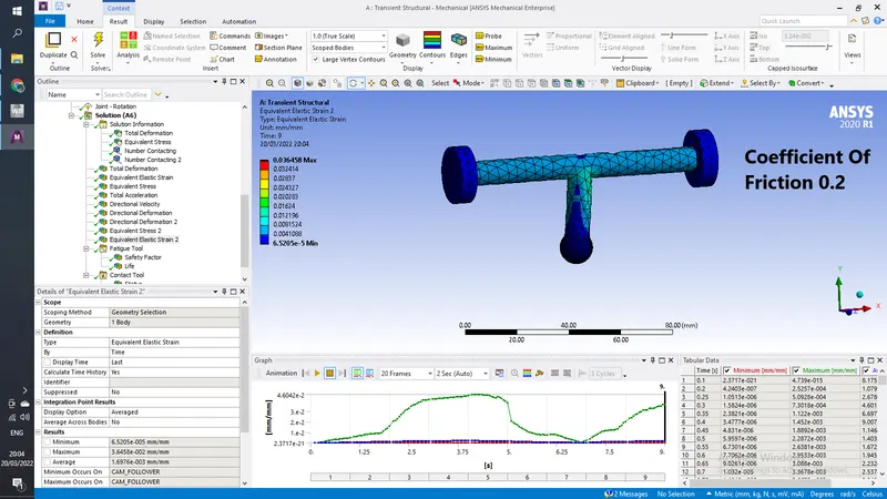
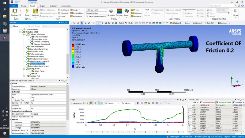
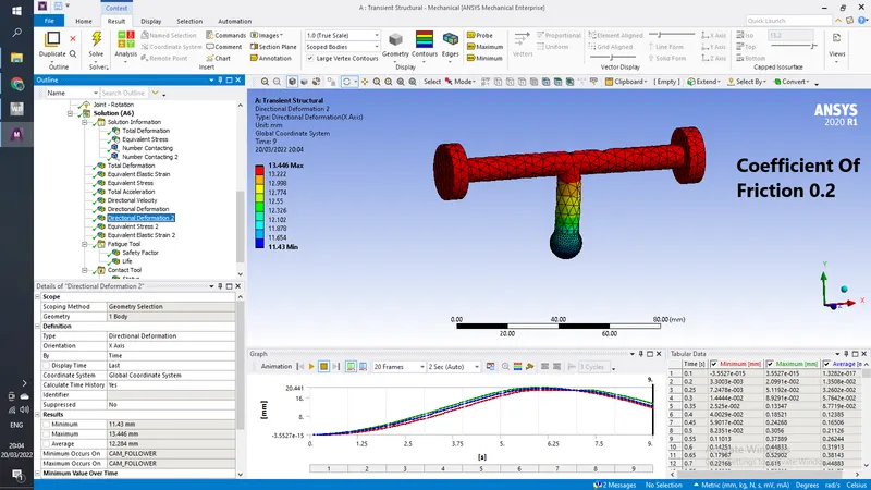
For this challenge, you will have to perform a transient analysis on a piston and cam mechanism model that has been provided to you. You need to run the analysis with Frictionless contact, Frictional with 0.1 and 0.2 as the frictional contact for a total of 3 cases. Find out the Equivalent Stress, Directional Deformation and Equivalent Elastic Strain and compare them for all the three cases. Give an inference as to why the results vary between cases.
Procedure-
1) Open Ansys Workbench and drag Transient Structural into project schematic
2) Import Geometry And open space claim to check if geometry have any abnormality or does it need cleanup, if everthing is correct , close spaceclaim
3) open Model to setup simulation, Here first go to geometry and make barrel cam and BARREL CAM as rigid bodies because we do not need to take them into account for results.
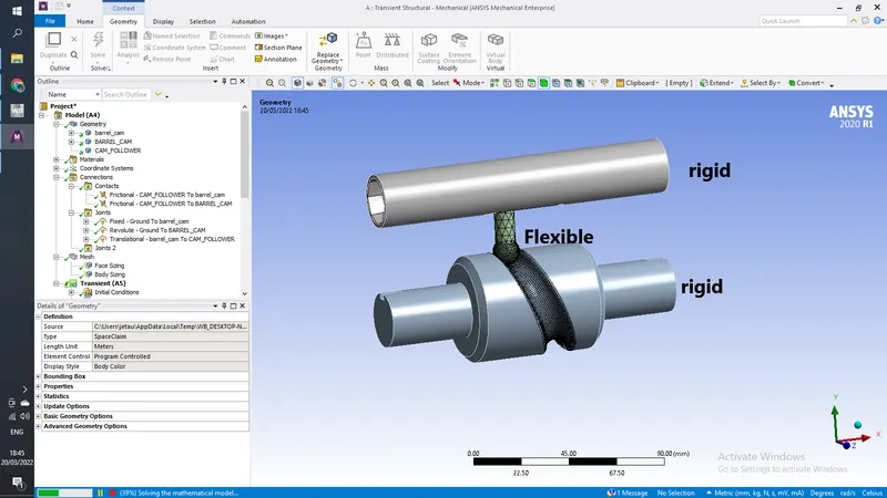
now go to connections and change existing connection to frictionless and reselect faces that are going to be in contact for the simulation
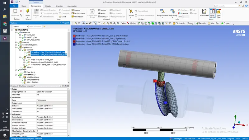
Now Insert
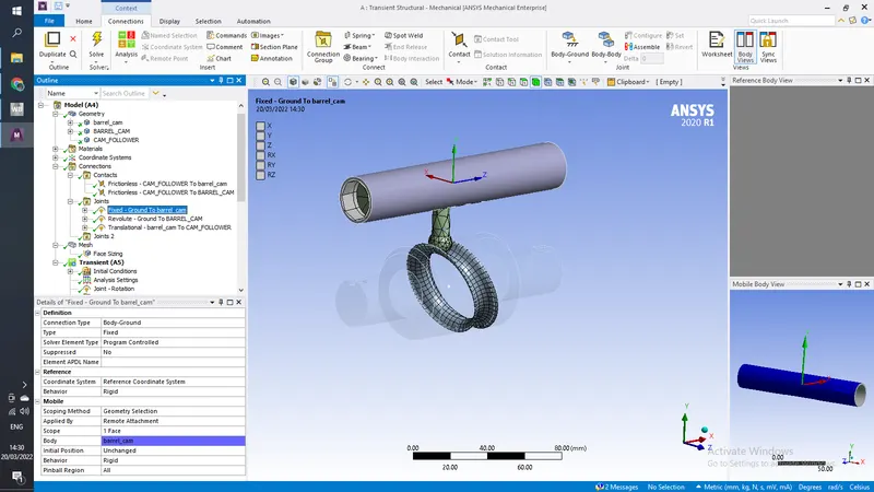
1. Body to ground fixed support to top barrel
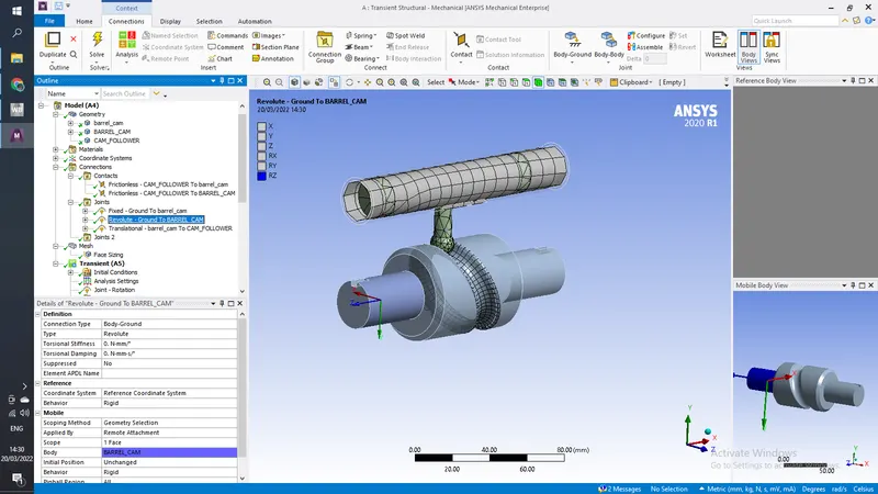
2. body to ground revolute joint to bottom barrel
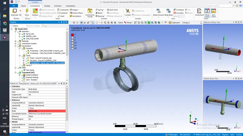
3. Body to Body Translation joint to top barrel and cam follower
In Mesh Add a body sizing of 4mm to cam follower and face szing if 1 mm to all the contact faces
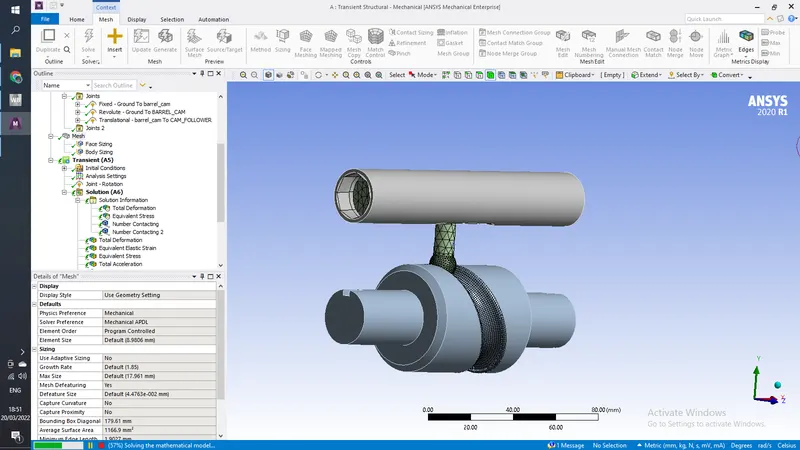
In Analysis Settings add 9 Steps with
for 1st step
Initial time step- 0.1
minimum time step- 5e-2
maximum time steo- 0.2
large deflection- on
weak spring - program controlled
stabaliztion - constant
energy decipatio ratio - 0.1
activation for 1st sub step- yes
for 2nd to 9th step
Initial time step- 0.1
minimum time step- 5e-2
maximum time steo- 0.3
large deflection- on
weak spring - program controlled
stabaliztion - constant
energy decipatio ratio - 0.1
activation for 1st sub step- yes
Now add revolute joint to the bottom barrel
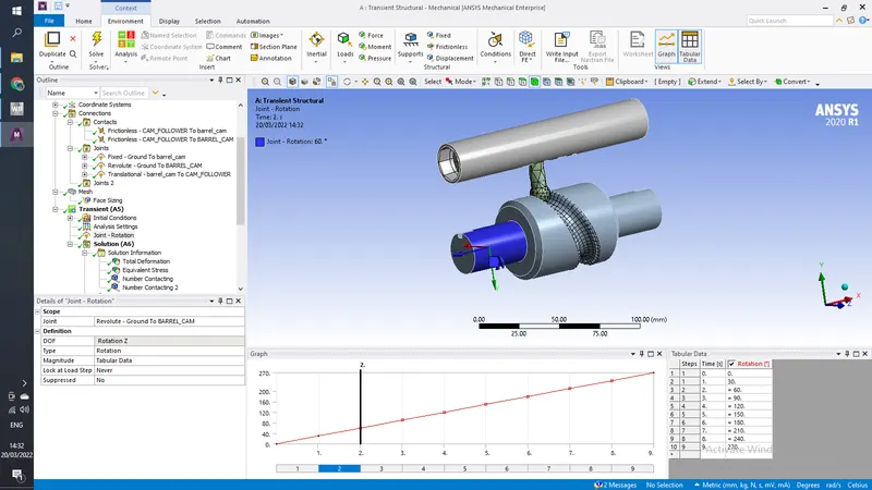
In Solutions add
Equivalent Stress, Directional Deformation and Equivalent Elastic Strain
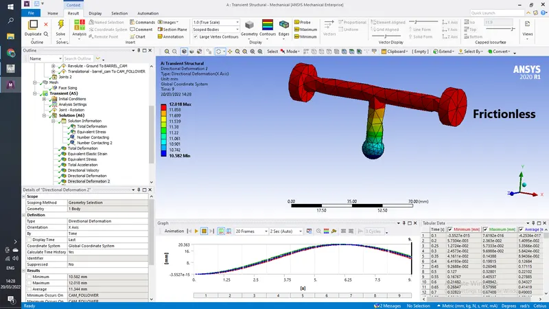
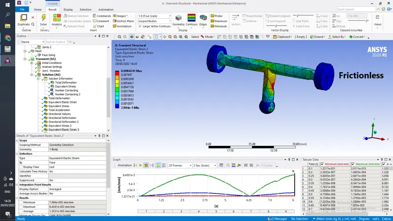
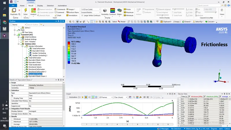
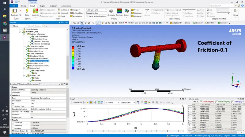
CASE 2
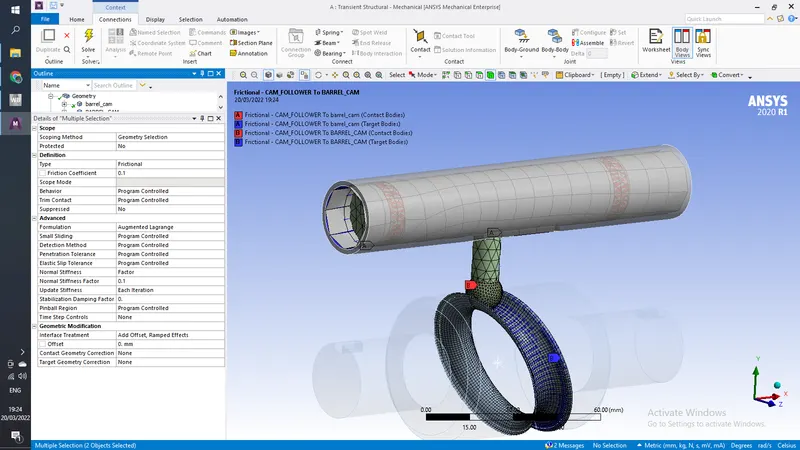
In this case we change the contact from frictionless to frictional
frictional coefficient -0.1
fromulation- Augmentend Lagrange
Normal Stiffness- Factor
Normal stiffness factor 0.1
upadte- each itration
interface treatment- add offset ramped effects
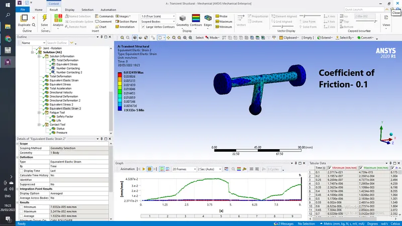
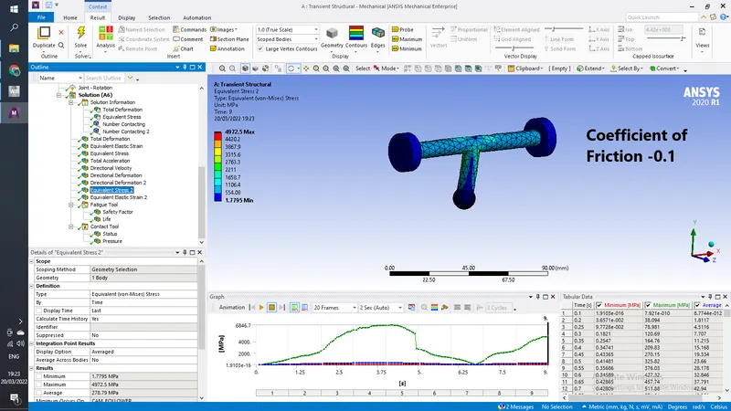
Results
CASE 3
Only Change Coefficient Of Friction to 0.2
Results