Week 7-Long Piston With Cam
Transient Analysis of Long piston with Cam mechanism using ANSYS Workbench:
AIM:
To study and perform transient analysis on the long piston with cam mechanism with given material and compare the analytical results. Grid dependency test was also performed to optimize the element size for better accuracy.
Case 1: Frictionless Contact on piston and cam mechanism.
Case 2: Frictional Contact of 0.1 on piston and cam mechanism.
Case 3: Frictional Contact of 0.2 on piston and cam mechanism.
TRANSIENT ANALYSIS SETUP FOR LONG PISTON WITH CAM:
I. GEOMETRY:
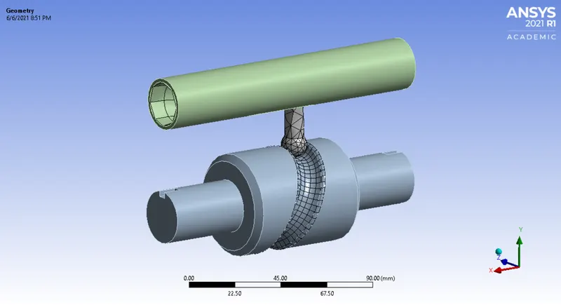
The CAD model of long piston with cam is imported in Ansys static structural environment. It comprises of three different components named as barrel, barrel cam, and cam follower. Here rotation, which is given as boundary condition to cam, which acts as boundary condition to cam, is acting as transient load. It constrains the follower to follow in the grooved portion and hence cause it to oscillate in the barrel. This whole motion is simulated in following analysis for three different cases in which the frictional nature of the contacting surfaces is changed. As, we have made stiffness behaviour for barrel and barrel cam as rigid.
II. MATERIALS:
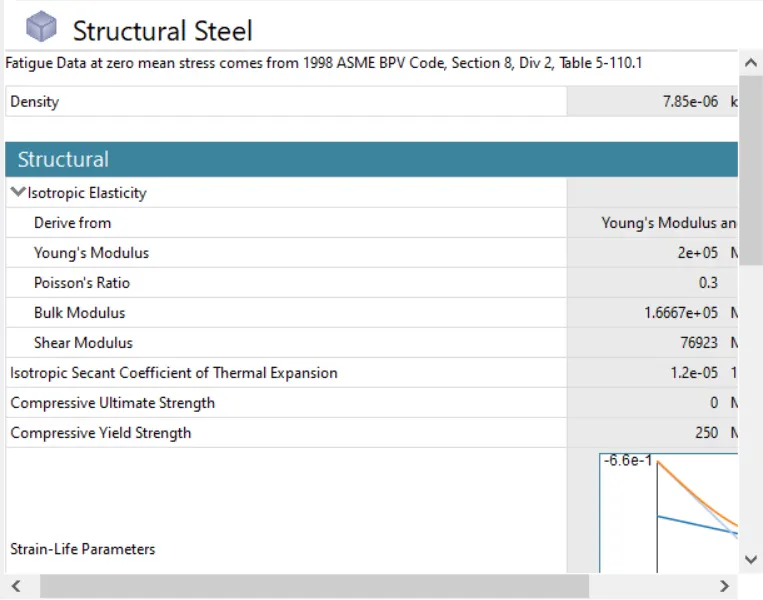
Below are the materials which is used to perform analysis for the long piston with cam mechanism. The analysis is carried out for each material individually.
Barrel: Structural Steel
Barrel Cam: Structural Steel
Cam Follower: Structural Steel
The details of each material has been carried out below as shown in the image:
III. CONNECTION DETAILS:
A. CONTACT DETAILS:
Case 1: Frictionless Contact on piston and cam mechanism:
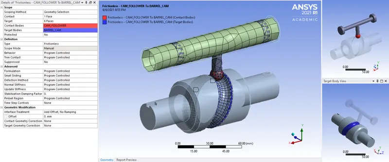
1. Frictionless-Cam Follower to Barrel Cam:
Frictionless contact is given below between faces of cam follower and barrel cam as shown in the image below. The 1 face of cam follower came in contact with 6 faces of barrel cam with type of contact as frictionless. Lastly, the scope mode is made to manual.
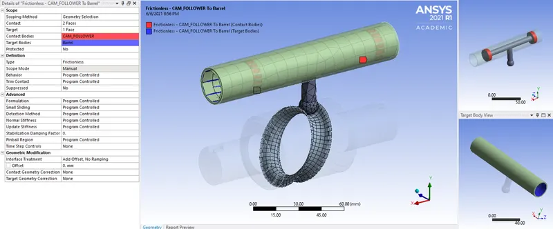
2. Frictionless-Cam Follower to Barrel:
Frictionless contact is given below between faces of cam follower and barrel as shown in the image below. The 2 faces of cam follower came in contact with 1 face of barrel with type of contact as frictionless. Lastly, the scope mode is made to manual.
Case 2: Frictional Contact of 0.1 on piston and cam mechanism:
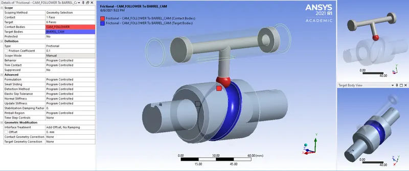
1. Frictional Contact (0.1) - Cam Follower to Barrel Cam:
Frictionless contact is given below between faces of cam follower and barrel cam as shown in the image below. The 1 face of cam follower came in contact with 6 faces of barrel cam with a frictional coefficient of 0.1. Lastly, the scope mode is made to manual.
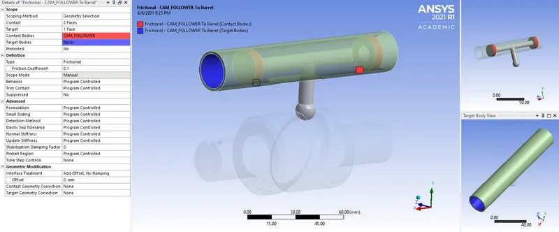
2. Frictional Contact (0.1) - Cam Follower to Barrel:
Frictionless contact is given below between faces of cam follower and barrel as shown in the image below. The 2 faces of cam follower came in contact with 1 face of barrel with a frictional coefficient of 0.1. Lastly, the scope mode is made to manual.
Case 3: Frictional Contact of 0.2 on piston and cam mechanism:
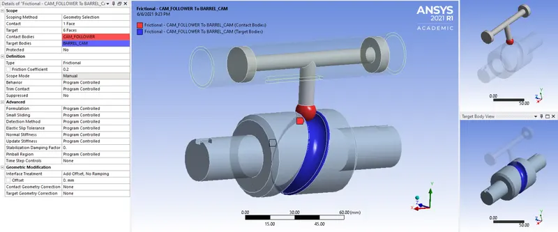
1. Frictional Contact (0.2) - Cam Follower to Barrel Cam:
Frictionless contact is given below between faces of cam follower and barrel cam as shown in the image below. The 1 face of cam follower came in contact with 6 faces of barrel cam with a frictional coefficient of 0.2. Lastly, the scope mode is made to manual.
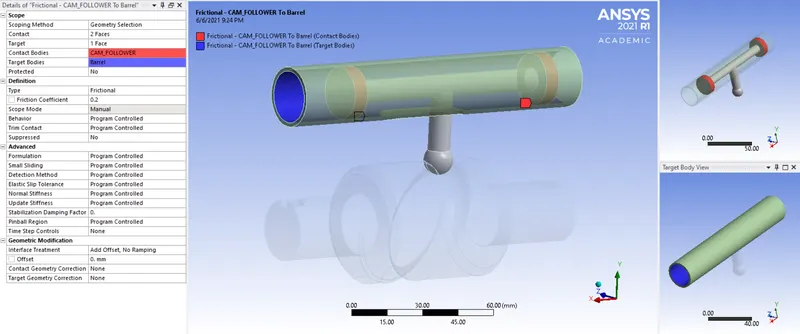
2. Frictional Contact (0.2) - Cam Follower to Barrel:
Frictionless contact is given below between faces of cam follower and barrel as shown in the image below. The 2 faces of cam follower came in contact with 1 face of barrel with a frictional coefficient of 0.2. Lastly, the scope mode is made to manual.
B. JOINT DETAILS:
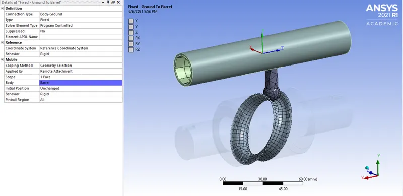
1. Fixed Joint-Ground to Barrel:
In this joint, we have to select the barrel as geometry selection part, as basically it holds relative to the ground so that it will not move while performing analysis. Then we have to change the connection type and connection as 'Body-ground' and 'Fixed'.
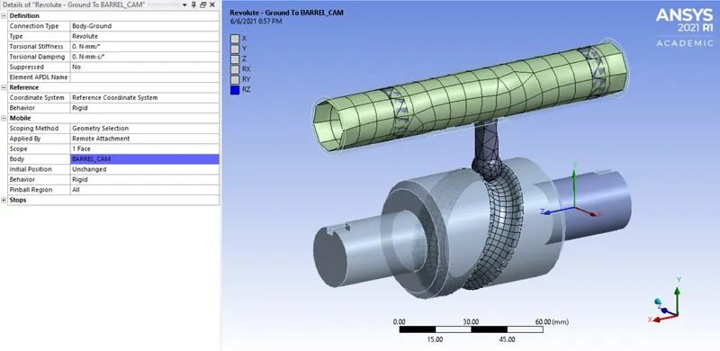
2. Revolute-Ground to Barrel Cam:
In this joint, we have to select the barrel cam as geometry selection part. Then we have to change the connection type and connection as 'Body-ground' and 'Revolute'. This joint is applicable to the cylindrical cam relative to the ground so that it will allow only axial rotation.
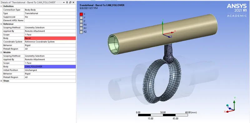
3. Translational-Barrel to Cam follower:
In this joint, we have to select the connection type and connection as 'Body-Body' and 'Translational.' Basically, we have selected reference body and mobile body type as 'Barrel' and 'Cam Follower' as its geometric selection part.
IV. MESH:
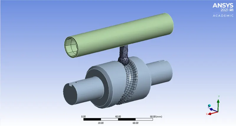
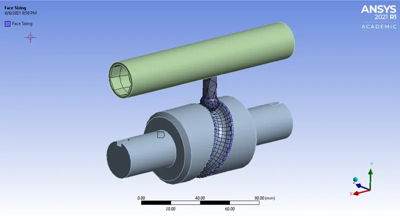
- Basically, we have preferred default mesh for whole setup.
- As, we have to do face sizing for the critical part, hence we have selected 7 faces as critical part and given element size as 3 mm.
- Likethat, we have generated the fine mesh which is sufficient to carrry out simulation which gives desired results.
V. ANALYSIS SETTINGS AND BOUNDARY CONDITIONS:
A. ANALYSIS SETTINGS:
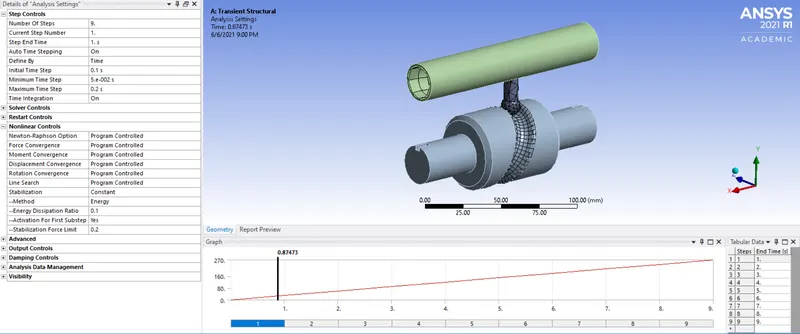
For this analysis the number of steps is set to 9 with Auto Time stepping is ON and it is defined by time, hence initial, maximum and minimum time will be 0.1, 5e-2, 0.2 sec respectively. After that, the solver type is to be Program controlled and then Large deflection is set to On, so as to account for change in stiffness due to change in shape of gears. When stabilizers are activated, it add dampers to all nodes. When the large displacement nodes try to move the force is added to balance them thus favoring convergence. Hence, the energy dissipiation is said to be 0.1. After that, we have enable the option for activation for first substep. Lastly, we have to enable all output controls to be ON.
B. BOUNDARY CONDITIONS:
Joint-Rotation:
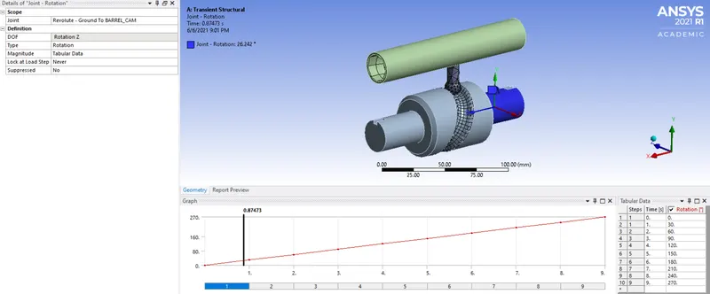
Basically, we have selected joint as Revolute-Ground to Barrel Cam. Then, we have taken DOF and its type as 'X Rotation' and 'Rotation'. Likewise, we have given rotation in tabular form. The rotation is given in the form of angle 30 deg.
VI. POST-PROCESSING RESULTS:
Now, we have to compare the deformation and stress on the basis of different materials. Then, we have to analyze the result for total deformation, equivalent stress and strain for Iphone bending. The results are as shown below:
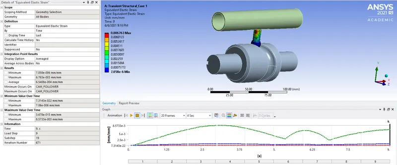
Case 1: Frictionless Contact on piston and cam mechanism:
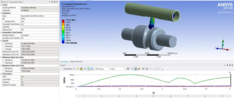
1. Equivalent stress:
2. Directional Deformation:
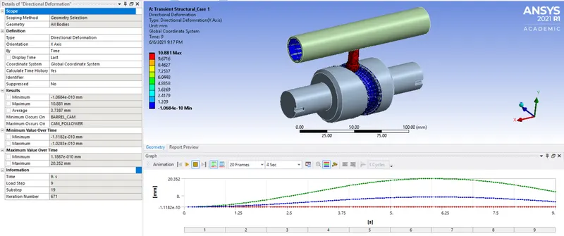
3. Equivalent elastic strain:
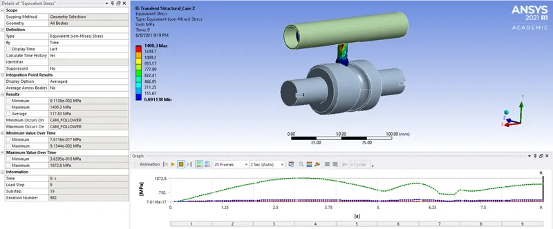
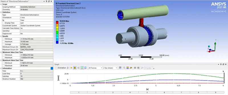
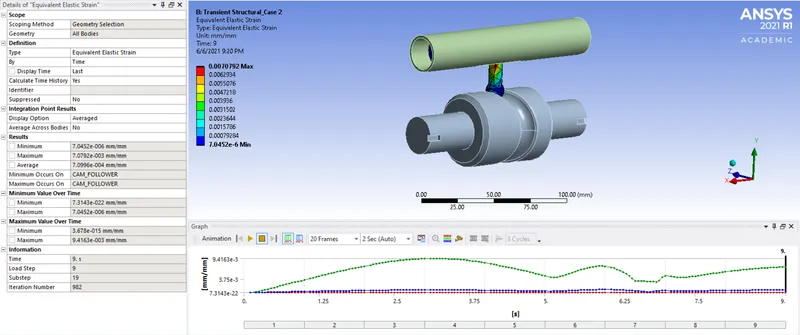
Case 2: Frictional Contact of 0.1 on piston and cam mechanism:
1. Equivalent stress:
2. Directional Deformation:
3. Equivalent elastic strain:
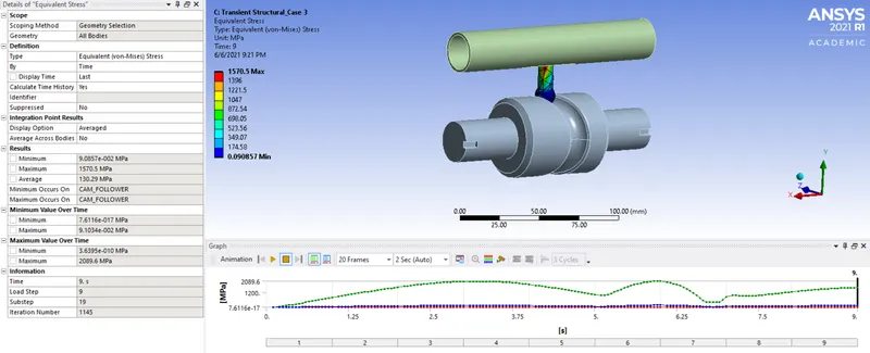
Case 3: Frictional Contact of 0.2 on piston and cam mechanism.
1. Equivalent stress:
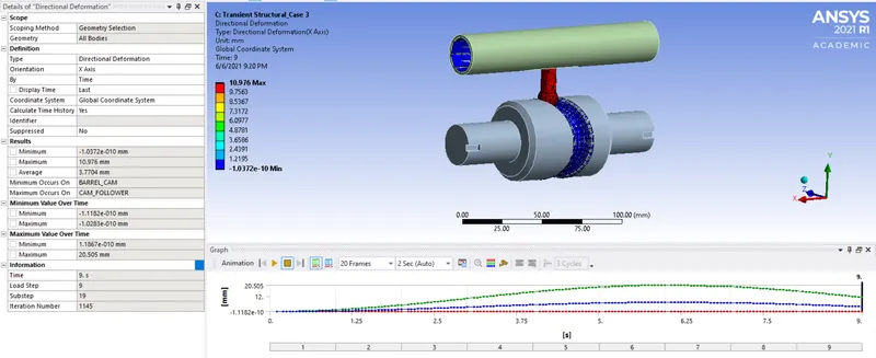
2. Directional Deformation:
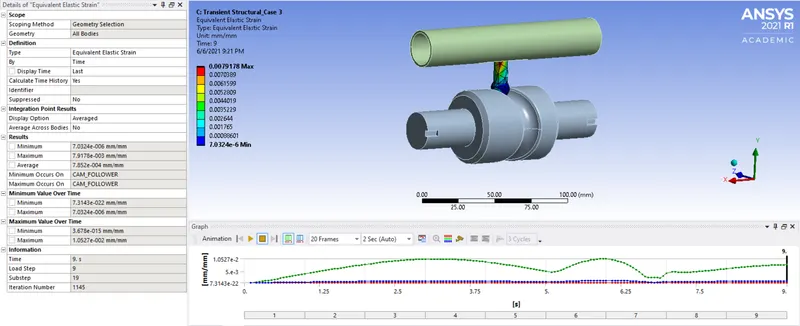
3. Equivalent elastic strain:
VII. POST-PROCESSING RESULTS:
|
Parameters |
Case 1 |
Case 2 |
Case 3 |
|
Maximum Directional Deformation |
10.881 mm |
10.926 mm |
10.976 mm |
|
Minimum Directional Deformation |
-1.0684e-010 mm |
-1.1514e-010 mm |
-1.0372e-010 mm |
|
Maximum Equivalent strain |
6.763e-003 mm/mm |
7.0792e-003 mm/mm |
7.9178e-003 mm/mm |
|
Minimum Equivalent strain |
7.058e-006 mm/mm |
7.0452e-006 mm/mm |
7.0324e-006 mm/mm |
|
Maximum Equivalent stress |
1337.1 MPa |
1400.3 MPa |
1570.5 MPa |
|
Minimum Equivalent stress |
9.1408e-002 MPa |
9.1138e-002 MPa |
9.0857e-002 MPa |
CONCLUSION:
- The transient analysis for piston and cam mechanism has been completed successfully with zero errors.
- When the contact type is frictionless, the surfaces are very smooth, contact forces are reduced and hence the stress and strain developed is less. Therefore, the deformation is also less.
- Here, the deformation refers to the displacement of the follower. The follower displacement is maximum in Case 3. This is because of increase in the stress and strain values due to the increase in the frictional coefficient. More forces are acting in Case 3 and hence the follower is pushed a little more.