Week 7-Long Piston With Cam
Objective – To run the simulation of the model Piston, cam & follower. Use various friction values & compare the results.
Case Setup & Execution:
- Open ansys workbench & drag Transient analysis.
- Click on engineering data and set the material as required.
- Next click on geometry. Import the geometry & open the same in space claim. Check for any visual defects in the model.
- Next up update the model & Click on edit.
- Now rename the parts of geometry as required.
- Make the barrel cam & barrel as a rigid support. Only the follower will be flexible.
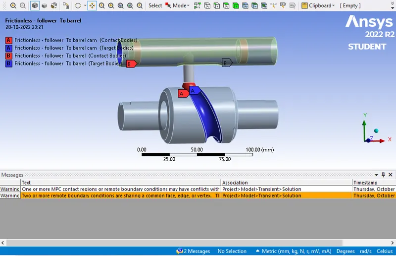
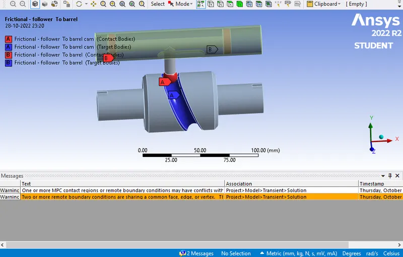
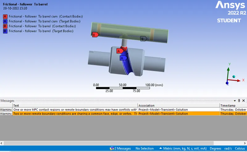
- Next in contacts make sure that two connections are present.
Barrel with follower - Barrel cam with follower.
Make sure that both the contacts are frictionless in the first case. For the 2nd & 3rd case add frictional values and then generate the results.
- Now add joints to the model. First insert a body-ground fixed joint to the barrel. Next add body-ground revolute joint to the barrel cam this is because it will rotate and then the transfer of motion will occur.
Also for the 3rd insert of body-body translational joint. Select barrel & follower as contact.
- Now in mesh insert sizing & select 3mm mesh size. Also make sure that adaptive sizing is off.
- In transient analysis let the number of steps to run the simulation be 8. In the first step change the settings as follows :
- Autotimer stepping to be on
- Change initial time step, minimum time step & final time step.
- Large Deflection on
- Stabilization Constant
- Energy Dissipation to 0.1
- Output Control to yes.
- Next now select step from 2 to 8 & change the time step as required.
- Insert a rotation joint & select the barrel cam. Add 30 degrees in each step from 0 to 9th step till 270 degrees.
- In solution add various output results such as Directional Deformation , Equivalent stress & Equivalent strain .
- Now Hit solve to let the simulation run .
Results :
|
Sr no |
Friction Contact Value |
Equivalent stress (MPA)(Max) |
Equivalent strain |
Directional Deformation (mm) |
Pressure (MPA) (Max) |
|
1. |
Friction less |
1682.2 |
0.008462 |
20.324 |
820.94 |
|
2. |
0.1 |
2123.5 |
0.007552 |
20.324 |
1110.4 |
|
3. |
0.2 |
2661.1 |
0.009091 |
20.359 |
1421.2 |
Case 1:
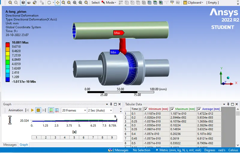
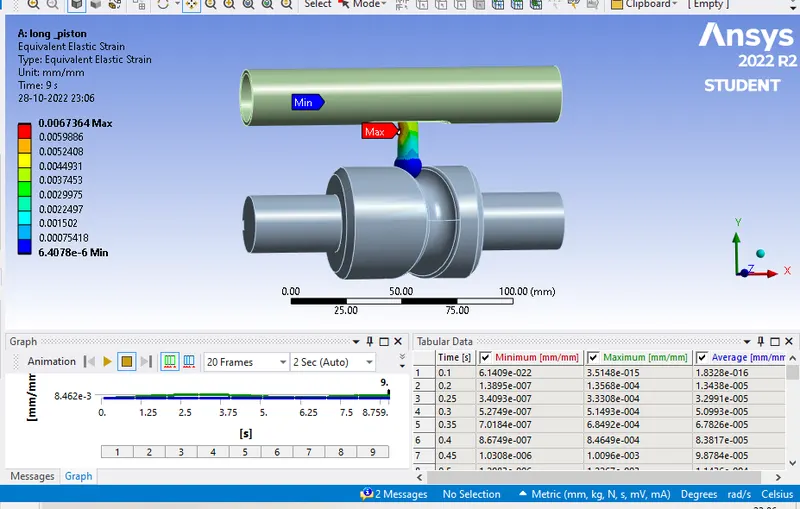
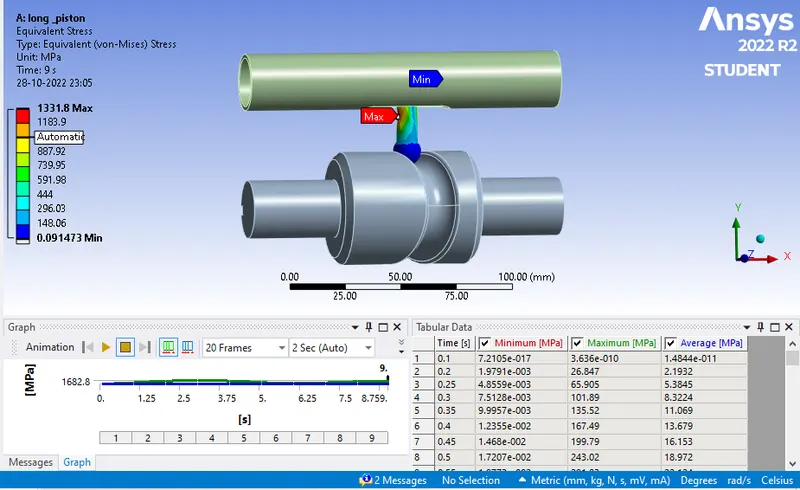
In this we have selected the two contact as frictionless contact. From the results it can be seen that an equivalent stress value of 1682.2Mpa & 0.008462 equivalent strain value is generated. Also directional deformation of 20.324mm is obtained. Pressure developed is 820.94Mpa.
Case 2:
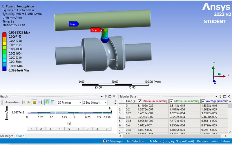
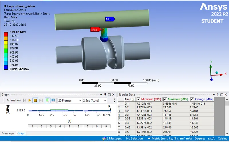
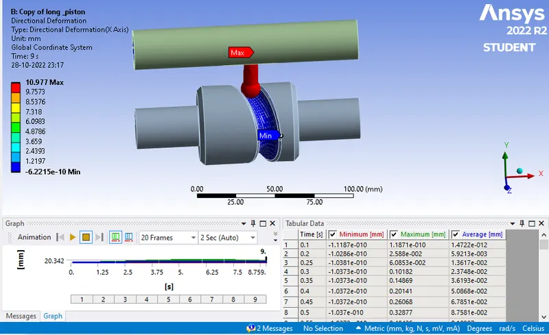
In this we have selected the two contact as frictional contact with a value of 0.1. From the results it can be seen that an equivalent stress value of 2123.5Mpa & 0.007552 equivalent strain value is generated. Also directional deformation of 20.324mm is obtained. Pressure developed is 1110.4Mpa.
Case 3:
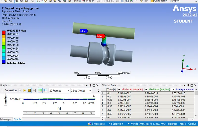
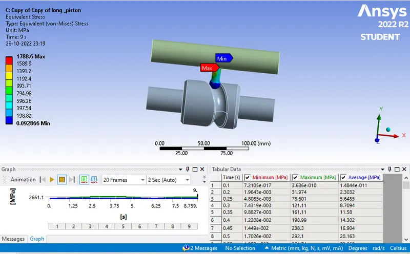
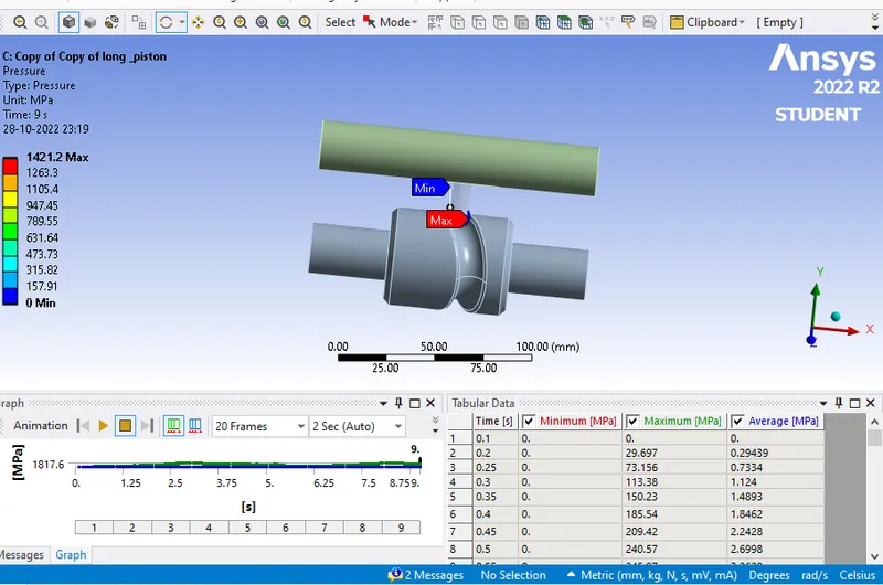
In this we have selected the two contact as frictional contact with a value of 0.2. From the results it can be seen that an equivalent stress value of 2661.1Mpa & 0.009091 equivalent strain value is generated. Also directional deformation of 20.359mm is obtained. Pressure developed is 1421.2 Mpa.
Conclusion :
From the tabular data shown above it can be observed that maximum stress value of 2661.1Mpa is generated where there is frictional value of 0.2 between the contacts. Where there is frictionless contact stress value generated is 1682.2Mpa. Next directional deformation is same all three cases as boundary conditions are same. Moving to Equivalent strain maximum strain value of 0.009091 is generated in case 3.Maximum pressure is observed in case3 following case2 & case1. So from the results we can say that when the contacts are frictionless stress & strain value are low as compared to 0.1 & 0.2 friction value. Friction Value creates resistance in the transfer of motion and thus develop stress in the body. So for the motion to transfer we have to always choose material which generates less cof value so that maximum efficiency can be obtained.