Week-7 Head Impact
Objective:
Pedestrian Head Impact
Pedestrian protection CAE is a part of vehicle safety engineering from a crash perspective. In pedestrian protection, we look for imparting minimum injury to the head, upper leg (thigh), and lower leg (including knee) in case of an accident with a human subject. These tests are usually done at a lower velocity from 20-40 kmph as accidents tend to result in more severe circumstances above these velocities and braking in case of an accident often results in collision at low velocities.
In this project, a children's head form model is provided. You are supposed to replicate a scenario where this head form will impact on a car bonnet. The bonnet should be considered as a rigid wall for the 1st case and while using the meshed hood model an elastoplastic material card has to be used. From the simulation, the head impact coefficient must be calculated manually and with the help of LS-PrePost.
The student has to perform the Head Impact Simulation and calculate the HIC value in the LS-PrePost.
- The student has to organize a multi-include file model using the keywords *INCLUDE, *INCLUDE_TRANSFORM, *DEFINE_TRASFORMATION.
- The Impact angle of the Pedestrian Head is between 35-75 degrees.
- Create a simple elastic material model for the simple head (meshed) that is provided.
The students are expected to start off with a simple head model and then add complexity step by step.
Submitting the head impact with the rigid and the head impact with Hood is expected.
Students should then replace the Rigid wall with the Hood and perform the same simulation with the Head foam.
Prepare a report of the simulation.
The report should contain the following,
- The impact simulation of a simple head impact with the Rigid wall.
- The impact simulation of the Head foam provided with the Rigid wall with the Stress / Strain plots and acceleration plot.
- The impact simulation of the head form with the Hood with the Stress / Strain plots and acceleration plot. For the hood, you can use Aluminium.
- The Stress / Strain plot from the Rigid wall simulation should be compared with the Stress / Strain plot from the Hood Simulation and there should be a detailed explanation if there is any difference in the plots.
Procedure:
Case 1
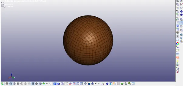
- Open Simple Head Model Input keyword file in LS – Prepost.
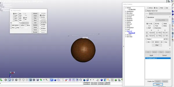
- Construct a Rigid Wall using Entity creation at the bottom of the wall, as the normal of the wall lies in the z-axis.
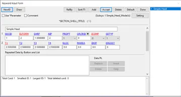
- Create Section Shell keyword for the shell elements with ELFORM =2 and thickness 2.5mm
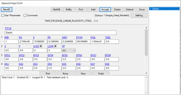
- Create the Material Keyword card with MAT_024 – Piecewise linear plasticity as Elastic with the properties as follows:
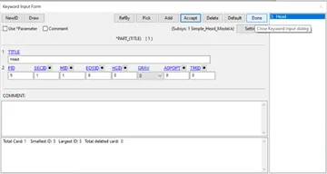
- Edit the Part keyword card with the created Section and Material assigned.
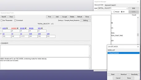
- Boundary Conditions – Assign Initial Velocity to the Node set created by selecting all the nodes of the sphere 40kmph – 11.11mm/ms in Z direction against the wall.
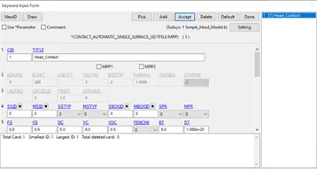
- Contact – Create an Automatic single surface self-contact card with having Head part as a slave.
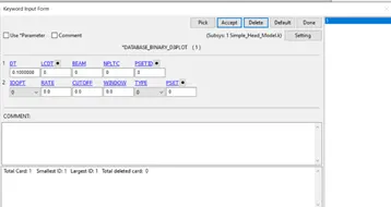
- Set DT – time step as 0.1 in Database_Binary_D3plot and add required ASCII files to the Database (GLSTAT, MATSUM, RWFORC, NODOUT).
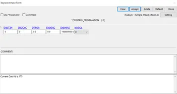
- Set ENDTIM as 5 ms in CONTROL – TERMINATION keyword card.
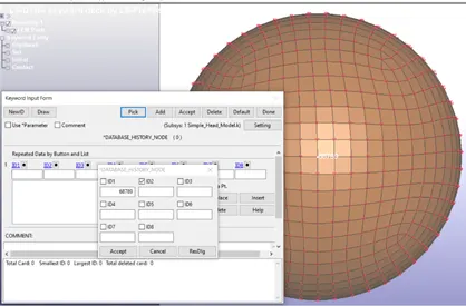
- Add Database – HISTORY NODE by selecting the bottom-most node for HIC calculation.
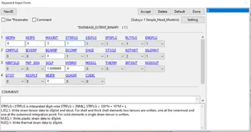
- Set STLRFLG =1 for strain calculation in the Database Extent Binary keyword.
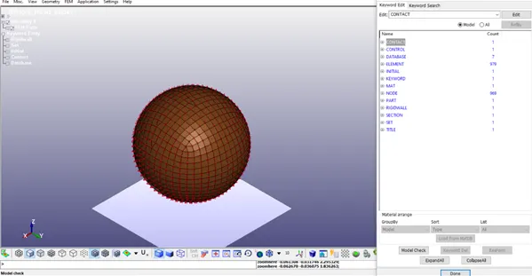
- Check the model for any errors and save the keyword in a separate folder.
- Run the Keyword file in LS – Run
- Open LS – PrePost, Import the D3 plot file created during the simulation.
- In the Fringe Component option, Select Von-mises stress for the contour plot and save the von mises animation videos – Select Strain for the contour plot – Maximum stress and strain is noted.
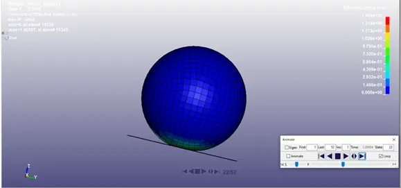
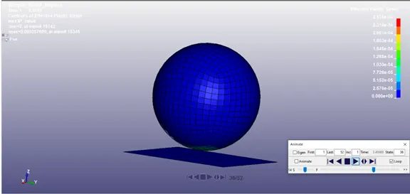
- Energy Curves – Plot Energy Curves using GLSTAT file
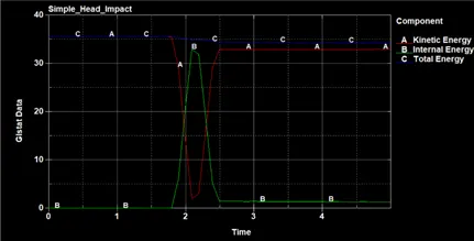
Kinetic Energy drops from 35.5 to 1.95 at 2.1 ms and then rises to 32.9 after the impact
Internal Energy increases to 32.9 at 2.1ms during the impact
Total Energy stays between 34.2 to 35.5 for the entire simulation.
- Plot the Total Acceleration and HIC 15, HIC 36 using the NODOUT file. (Make sure the settings are consistent with correct units for HIC)
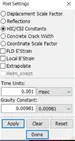
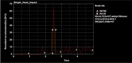
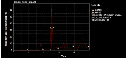
HIC = 3.548e7
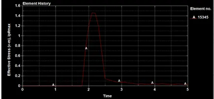
- Plot Effective Plastic Strain and Von - mises Stress graph selecting an element 15345.

Case 2
- Open Pedestrian_headform Model Input keyword file in LS – Prepost.
- Add Define transformation keyword card to rotate the head in the Y axis of 45°
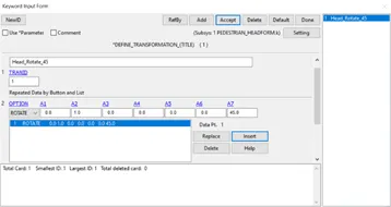
- Add INCLUDE – TRANSFORM card by selecting the original file and assigning the transformation card.
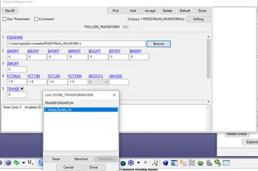
- Save the Keyword input file in a Separate folder and import it again in LS – Prepost separately to view the transformation of the Head (Rotated Head).
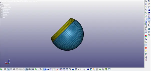
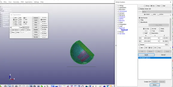
- Construct a Rigid Wall using Entity creation at the bottom of the wall, as the normal of the wall lies in the z-axis.
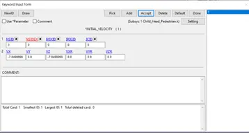
- Boundary Conditions – Assign Initial Velocity to the Node set created by selecting all the nodes of the sphere 40kmph – 11.11mm/ms – separated as components 7.85mm/ms (45°)
- Set ENDTIM as 10 ms in CONTROL – TERMINATION keyword card.
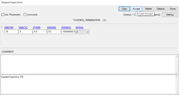
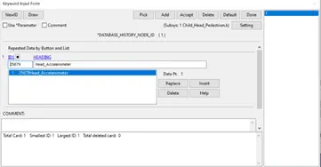
- Check Database – HISTORY NODE for HIC calculation. (Delete the parent history node if any)
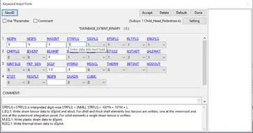
- Set STLRFLG =1 for strain calculation in the Database Extent Binary keyword.
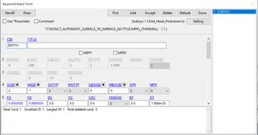
- Contact – Check Automatic single surface - contact card.
- Set DT – time step as 0.1 in Database_Binary_D3plot and add required ASCII files to the Database (GLSTAT, MATSUM, RWFORC, NODOUT).
- Check the model for any errors (Delete the extra files from the parent keyword file if any error) and save the keyword file.
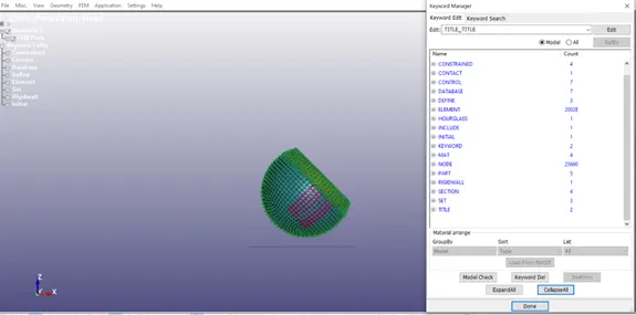
- Run the Keyword file in LS – Run
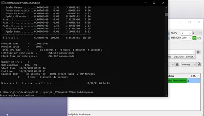
- Open LS – PrePost, Import the D3 plot file created during the simulation.
- In the Fringe Component option, Select Von-mises stress for the contour plot and save the von mises animation videos – Select Strain for the contour plot – Maximum stress and strain are noted.
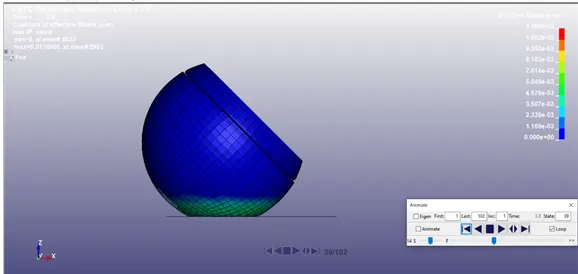
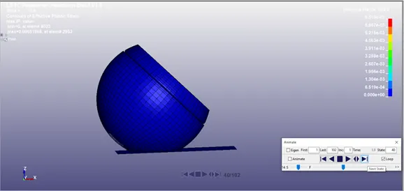
- Energy Curves – Plot Energy Curves using GLSTAT file
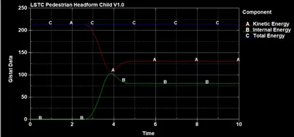
Kinetic Energy drops from 214 to 107 at 3.9 ms and then rises to 131 after the impact
Internal Energy increases to 104 at 3.9 ms during the impact and falls to 80
Total Energy is almost constant with 214 for the entire simulation.
- Plot the Total Acceleration and HIC 15, HIC 36 using the NODOUT file. (Make sure the settings are consistent with correct units for HIC)
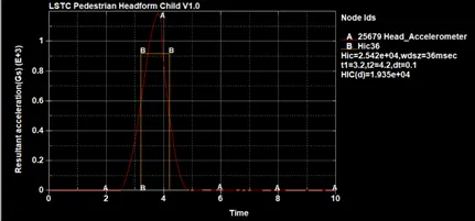
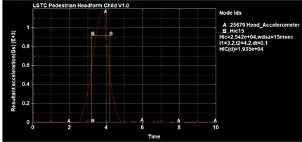
HIC = 1.935e4
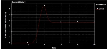
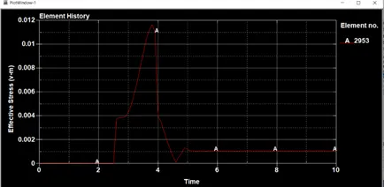
- Plot Effective Plastic Strain and Von - mises Stress graph selecting an element 2953.
Case 3
- Copy the given Meshed_hood.k file to a separate folder. Now Copy the keyword file of the Child -pedestrian head file created from case 2 to the same folder. Open that Pedestrian child head file and delete the rigid wall and save it.
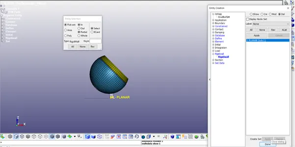
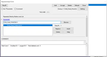
- Open the Meshed_hood keyword file in LS- Prepost, Now using Include – Include keyword add the child pedestrian edited one.
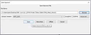
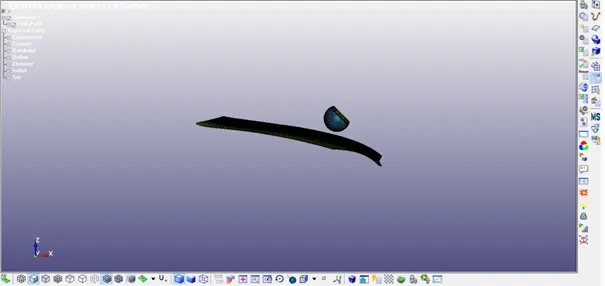
- Save the Keyword input file in the same folder and import it again in LS – Prepost separately to view the child head and hood.
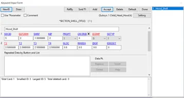
- Create Section Shell keyword for the shell elements with ELFORM =2 and thickness 2.5mm
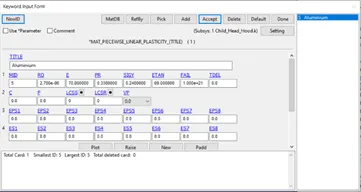
- Create the Material Keyword card with MAT_024 – Piecewise linear plasticity as Aluminium with the properties as follows:
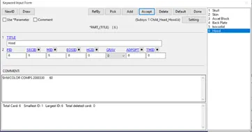
- Edit the Part keyword card with the created Section and Material assigned.
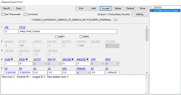
- Contact – Create an Automatic surface to surface contact card with having Hood a master & Head part (created using Set_Part) as a slave.
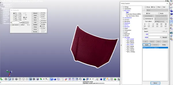
- Boundary Conditions – All the nodes of the outermost hood is constrained in all direction to make the hood intact.
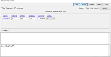
- Set ENDTIM as 50 ms in CONTROL – TERMINATION keyword card.
- Check the model for any errors (Delete the extra files from the parent keyword file if any error) and save the keyword file.
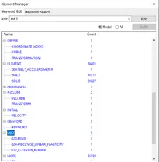
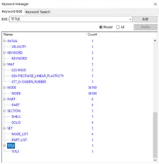
- Run the Keyword file in LS – Run
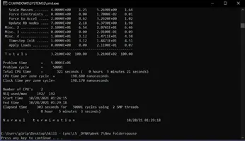
- Open LS – PrePost, Import the D3 plot file created during the simulation.
- In the Fringe Component option, Select Von-mises stress for the contour plot and save the von mises animation videos – Select Strain for the contour plot – Maximum stress and strain are noted.
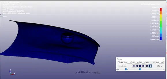
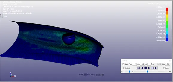
- Energy Curves – Plot Energy Curves using GLSTAT file
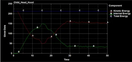
Kinetic Energy drops gradually from 214 to 49.5 at 15.4 ms and then rises to 160 after the impact
Internal Energy increases gradually to 150 at 15.4 ms during the impact and falls to 36
Total Energy is almost constant with 214 for the entire simulation.
- Plot the Total Acceleration and HIC 15, HIC 36 using the NODOUT file. (Make sure the settings are consistent with correct units for HIC)
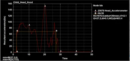
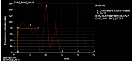
HIC15 = 714.4
HIC36 = 903.4
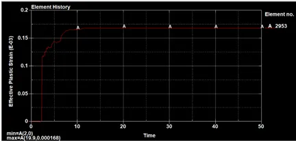
- Plot Effective Plastic Strain graph selecting an element 2953.
Learning Outcome:
Defining Include Keyword and Transformation
Understanding HIC curves during the impact.