Week-7 Head Impact
Pedestrian protection CAE is a part of vehicle safety engineering from a crash perspective. In pedestrian protection, we look for imparting minimum injury to head, upper leg (thigh), and lower leg (including knee) in case of an accident with a human subject. These tests are usually done at a lower velocity from 20-40 kmph as accidents tend to result in more severe circumstances above these velocities and braking in case of an accident often results in collision at low velocities.
Objective: To Perfom head impact on the three different cases and compare the three different results
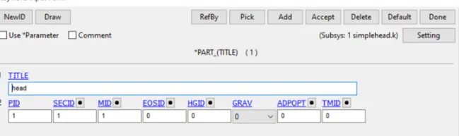
Procedure: The Simple head model was imported and was having only few keywords which were found to be insufficient for the simulation
Case 1:Simple Head imapct on Rigid wall
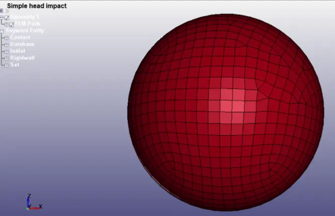
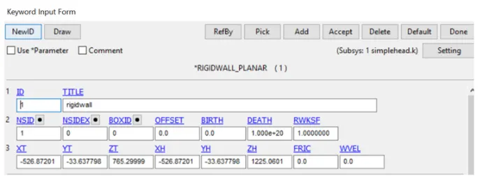
1.Firstly one rigid wall was created in the base of the Head such that the head impacts on the RWALL
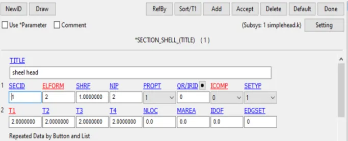
2.Then section properties is created as section shell Card , keeping the thickness as 2 mm for the shell elements
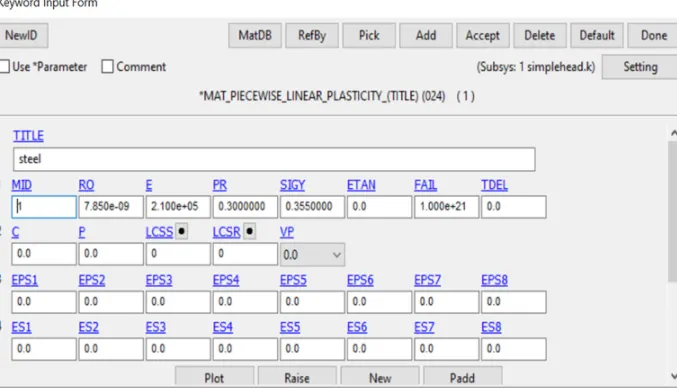
3.The material card is used as MAT_24_linear piecewise plasticity and assigned steel properties
4.Then after creating MAT and section these properties were assigned to PART
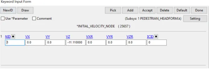
5.Then after this initial velocity was assigned to the model and the Node set was created and the NSID was assigned Initial Velocity
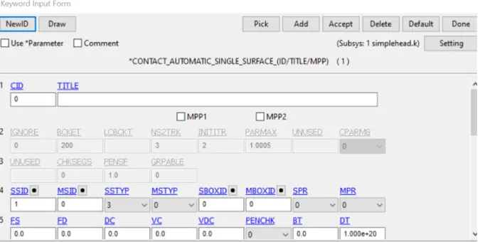
6. Contact was to be assigned to the model The single surface automatic contact was assigned to the model and Slave ID was created using the Shell elements and no Master was defined as it was
 .
.
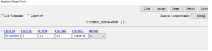
7.After creating the contacts the Termination time and Database was assigned to the model
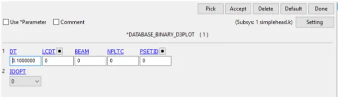
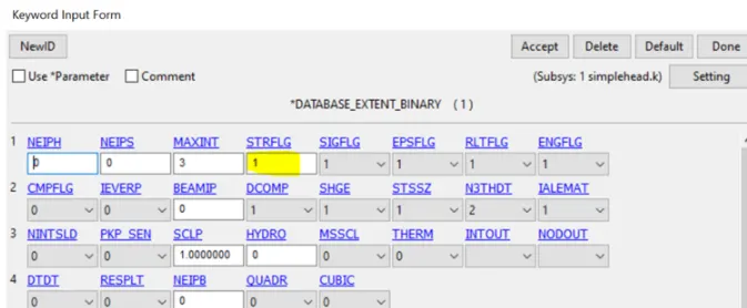
10.Then after setting all the Keywords the Simulation was run Using LS Run
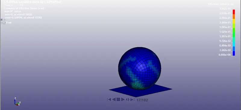
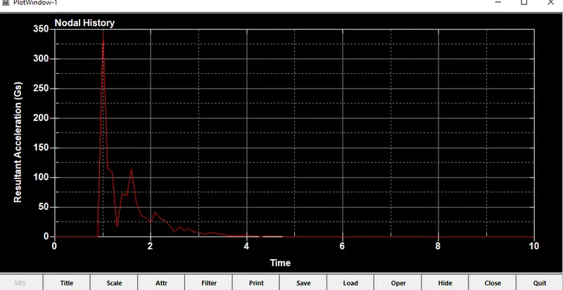
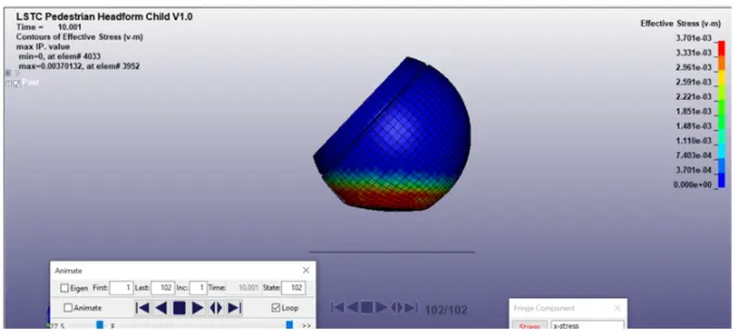
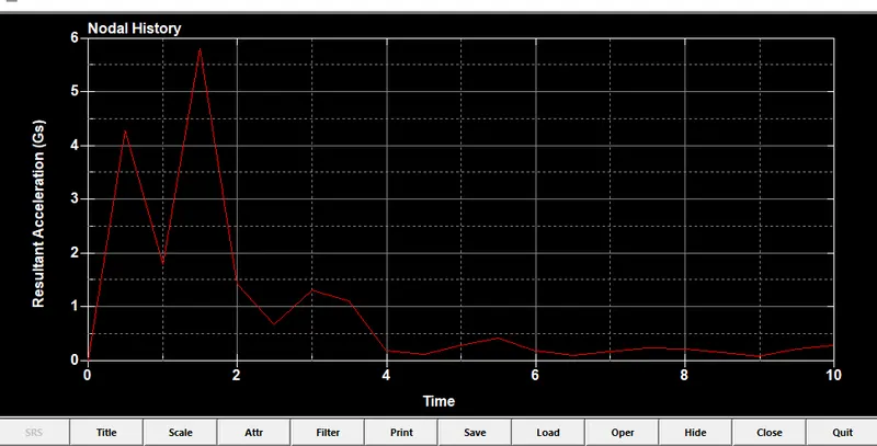
The HIC was Calculated using Nodal history plot and we can see that the Nodes are Resulting high Stress during the start of the simulation and further the stress lowers as the head bounces back
Case 2: Pedestrian Headfoam imapcting on the Rigidwall
The standard model of Child Headform is provided below
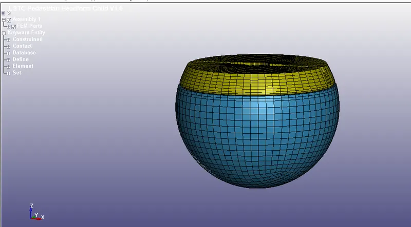
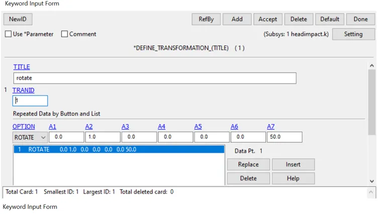
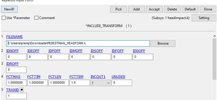
In this model the imapct angle about 50 deg was created against the rigid wall and this can be done by Include transform and Define transform Keywords
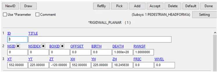
1. The rigid wall was created at 10mm from the bottom nodes of the model and this was done Rigidwall Keyowrd
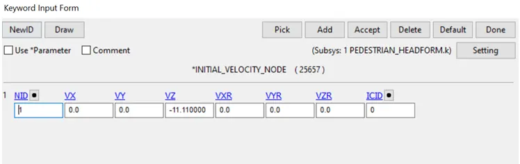
2.The geometry was supposed to be having some initial velocity so that it collides against the Rigidwall, A node set was cretaed using Set nodes and vleocity was assigned to the model
The initial velocity keyword was used for assigning the vleocity(11.11 m/s)
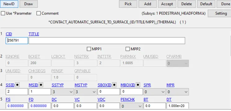
3.Then in this case Contact of Automatic surface to surface was defined between the solid parts
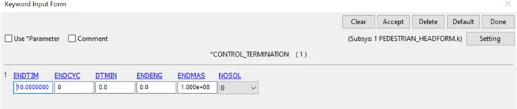
4.Control termination card was used to define the end time of the simulation
5.Then after this ASCII_output like Glstat,Nodout,RCForc was define with 0.1 ms time step
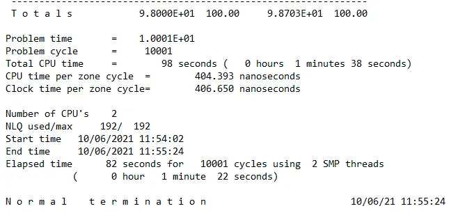
6. Then finally the simulartion was run Using LS Run
Von Misses stress
Resultant acceleration HIC 36
Case 3.Pedestrian Headfoam impacting against the Hood
The hood model was opened and was not having pedestrian hence it was introduced with include keyword
The pedestrian was rotated about 45 deg towards the hood for collision and this was done by include transform and define transform
The hood was modeled with Mat 20 with alluminium properties and sectional shell thickness of 1 mm
The contact automatic surface to surface was defined between hood and pedestrian
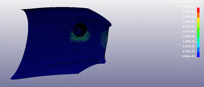
The below is Von-misses stress plotted for the case
The HIC value recorded in accelerometer was plotted on the graph below .
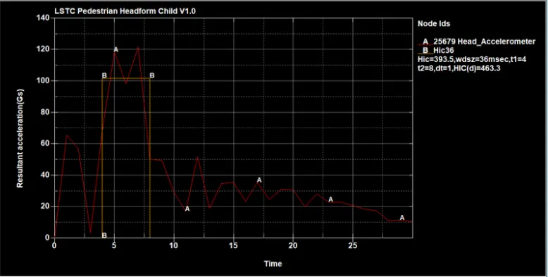
The HIC value is recorded as 393.5 which is less than the HIC 6650 value
Conclusion : Hence studied three different cases of head impact and Calculated some effective results
Drive Link for case file:https://drive.google.com/drive/folders/1G0VFtTECw7qqHTruL3cYODBnEYxpIMd-?usp=sharing