Pedestrian Head Impact Simulation using LS-Dyna
AIM:- Pedestrian Head Impact Simulation using Child's head form in LS-Dyna.
Objectives:-
- The impact simulation of a simple head impact with the Rigid wall.
- The impact simulation of the Headform provided with the Rigid wall.
- The impact simulation of the head form with the Hood.
- Calculate the HIC value and cross-check with the plot result.
- Assure the Less HIC for Pedestrian safety.
Introduction:
Pedestrian protection assessment methods require multiple head impact tests on a vehicle’s hood and other front-end parts. Hood surfaces are often lifted up by using pyrotechnic devices to create more deformation space prior to pedestrian head impact. Assessment methods for vehicles equipped with pyrotechnic devices must also validate that the hood deployment occurs prior to the head impact event. Estimation of pedestrian head impact time, thus, becomes a critical requirement for performance validation of deployable hood systems. In absence of standardized physical pedestrian models, Euro NCAP recommends a list of virtual pedestrian models that could be used by vehicle manufacturers, with vehicle FEA (Finite Element Analysis) models, to predict the potential head impact time along with the vehicle front end profile. FEA simulated contact time is used as a target for performance validation of sensor and pyrotechnic deployable systems. While the current FEA-based process is a reasonable one, it can be further simplified by defining the expected contact time as a function of geometric parameters of a vehicle’s front-end profile. In fact, this proposed simplified method is an extension of the current global pedestrian impact assessment methods, where vehicle geometric parameters are used to define target impact zones, impactor types, and impactor energy.
Currently in India Automotive Indian Standard 100 (AIS 100) Amendment 1&2 is used to evaluate the performance of the vehicle against Pedestrian Safety. This Standard has been harmonized from the International Evaluation Standard, Global Technical regulation-9 (GTR-9), Whose purpose is to bring about an improvement in the construction of the Frontal of the vehicle precisely. Those areas are most frequently identified as causing injury when in collision with pedestrians or other vulnerable road users.
The Tests are focused on those elements of child and adult bodies most frequently identified as sustaining an injury i.e. adult head and legs and child's head. To achieve the required improvements in the constructions of the vehicle, The tests are designed in such a way that they will represent the real-world accident scenario.
[ REFERENCE:- Aerometrex YouTube channel ]
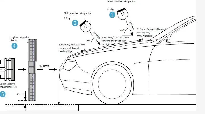
Different types of impactors are used to represent the different parts of the body. Like in a Pedestrian collision most common body parts that have come into contact with the vehicle during a collision are Leg and head. In that also the Head Injury considered as crucial among all. As per the image shown above, there is Legform, and Child and Adult head Forms are setup. Each impactor is impacted using the velocity defined by the particular standard. Under this study, we are seeing AIS 100.
Wrap Around the Distance
When the car Crash's on a Pedestrian, the Whole human body wrap around the Front shape of Car and the Head impacts the bonnet/Hood or windshield. the distance at which the head impacts on the car from the ground is known as Wraparound distance.
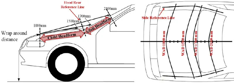
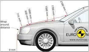
The Wraparound distance measure longitudinally in the center of the vehicle from the ground. The severity of the injury depends upon the various factor like the shape of the vehicle, Speed of the vehicle, At what angle the pedestrian impacted to stopping the car, etc and in all of this WAD play a major role.
During the Head impact test on the bases of WAD, the car frontal Area (Impact zone) divided into two-zone,
1)Child Impact Zone:- The Impact Zone is between 1000mm to 1700 mm WAD
2)Adult impact zone:- The Impact Zone is between 1700mm to 2100 mm WAD
Head Impact Criteria (HIC)
In the head Impact test, the severity of the pedestrian impacted depend on the location of the impact over the hood and the velocity with which it impacted. As per the standard, The test conduct with the headform velocity of 35km/hr and the angle of impact is set to be 50 degrees.
The Head impact Criteria is the criteria that determine the severity of the injury by calculating Avg. Acceleration and multiply with the Time difference. There is special Eq is there to Satisfy the HIC,
`HIC= max_(t1,t2) [1/(t2-t1) int_(t1)^(t2). a(t)dt]^2.5* (t2-t1)`
a= Average Acceleration.
t2,t2= Time interval for which HIC get calculated.
For example, At HIC=650,
90% probability of level 1,
55% of level 2.
20% of level 3.
5% of level 4.
-small HIC value doesn't mean that the head injury will be low level.
-Likewise, a High HIC value doesn't mean a High level of injury. the real meaning is that, with higher the HIC value the Higher the probability of getting high-level head injuries.
Abbreviated Injury Scale (AIS):
Level 1: Slight damage to the brain with headache, dizziness, no loss of consciousness, confusion.
Level 2: Concussion with or without skull fracture, less than 15 minutes of unconsciousness, detached retina, face, and nose fracture.
Level 3: Concussion with or without skull fracture for more than 15 minutes of unconsciousness without severe neurological damage, multiple skull fractures. loss of vision, multiple facial fractures, cervical fracture without damage to the spine:
Level 4: Multiple skull fractures with severe neurological damage.
Level 5: Concussion with or without skull fracture, more than 12Hr of Unconsciousness, Hamorrhage in the skull, and critical Neurological Condition
Level 6: Death, Critical factor with damage to the spine.
Procedure
Under this project, we have work on Three cases those are respectively
CASE1:- This case is a case of a simple drop test where the user has to drop the ball over the ground.
We can easily set up the case for the ball dropping over the ground horizontally, we only have to define the "Initial Velocity" in the direction we want to move the ball.
Here I am Trying to Introduce new Cards that give us the freedom to give direction and set the part as per the co-ordinate we wanted. This means we can drop this ball at an inclined angle also.
Here we are gone a look into some of the "Define" & "Include" Cards.
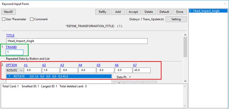
The First one is the "TRANSFORMATION" Card from the Define. Using this card we can transform the entire system as we want. There are lots of options available for transformation like rotate, scale, mirror, etc.
The A1, A2, A3, A4, A5, A6 Rotate through an angle (deg), a7, about aline with direction cosines a1, a2, and a3passing through the point with coordinates a4, a5, and a6. In simple words, A7 is to define require a degree to which we want to rotate the file, and A1, A2, A3 are the Axis of Rotation.
(NOTE:- Here we are using Rotate operation that why the A7 representing angle and the other parameter representing the Axis of rotation. The Significance of this Parameter will change as per the operation choose to perform. In most of the Cases these A1 to A6 parameters represents the Directional Vectors )
We can only use this card along with INCLUDE_TRANSFORM where we can Include the file (Part, assembly, system, etc) we want to Transform.
The TRANSID (Transformation ID) is one of the important things in this card. As shown in the below images the same trans Id which had defined in the Define-transformation Card have been called in the Include- Transform Card also. (Highlighted with Green box)
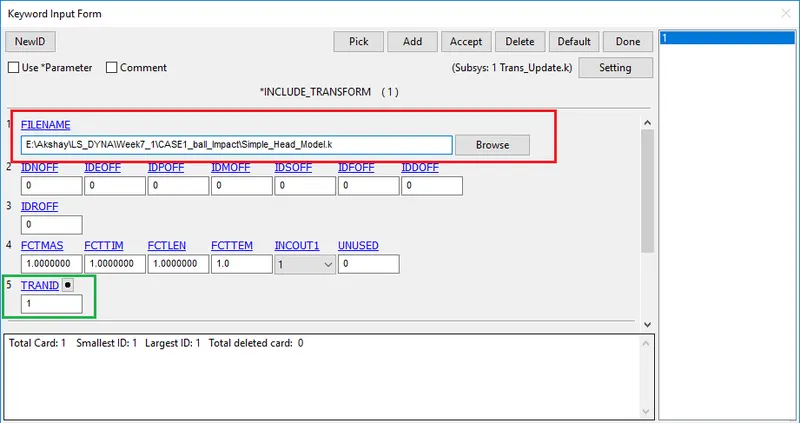
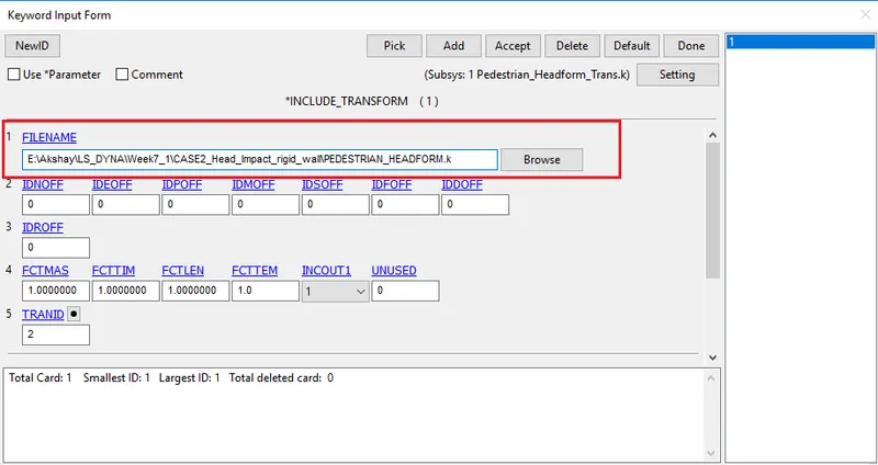
INCLUDE_TRANSFORM used for calling the file we want to Transformed. As the Ball model file saves under the name of "Simple_head_model" we can see that file in the Filename window.
*The Tricky part here is after completion of the procedure you can't able to see the end results until you save the file as a new file and again open it using LS-Pre post.
I had saved the file under the name of "trans_update", reopen it and from here start to set up the CASE by giving contacts, Boundary conditions, etc.
Here is the file After Re-opening,
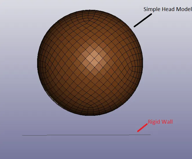
It's hard to notice the angular translation here as the object is in round shape, but by the pattern of the mesh, we can say that the ball is tilted at an angle of 45 degrees.
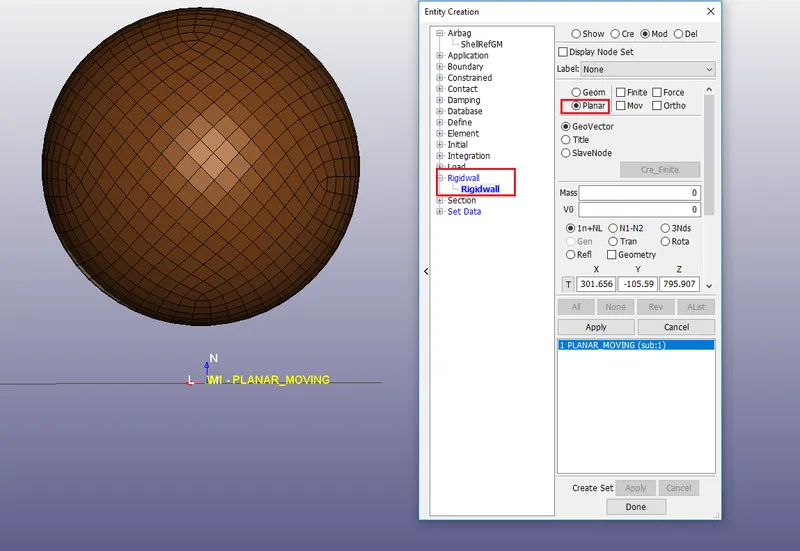
2) The second step is to define the Rigid wall
-Defined the rigid wall using the Entity Creation. the most important thing to note here is the normal direction of a plane, As you can see in the image the Normal is pointing opposite to the direction of fall.
3)Material Cards and Section card
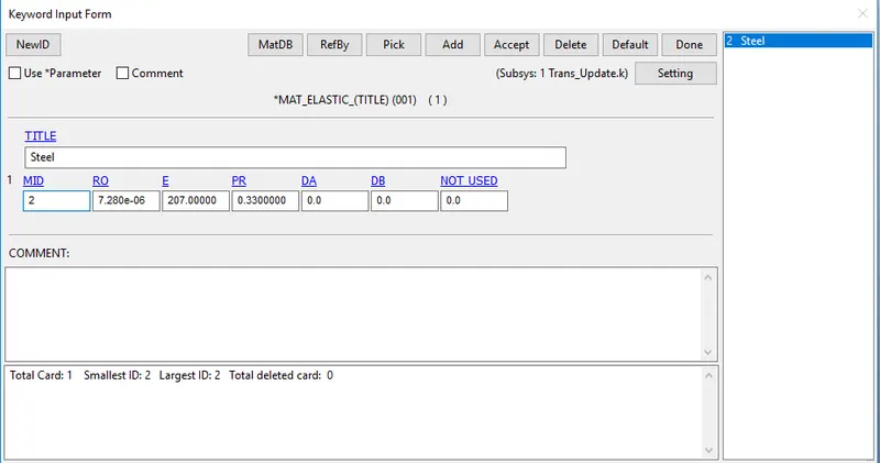
For this case, I have decided to go with Steel material. I had defined the material using Elastic Material Card-MAT001
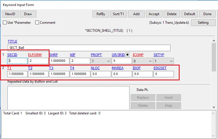
Section Card with a thickness of 1.5mm along with the Element formulation 2 which is the reduced integration type of formulation.
4) Contact Definition
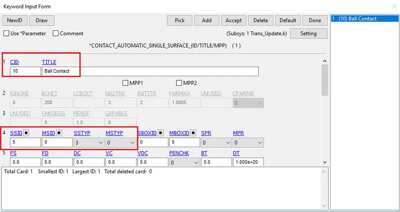
Contact definition is needed for the proper execution of the simulation as we are studying how is the ball made of steel behaves when landed on the ground at a 45dgrees angle. A proper contact interface should be there. I had used the "Automatic-Single-Surface" contact and defined the ball Nodset as the slave one. In Automatic-Single-Surface we don't have to define the master segment it will automatically consider the Wall as a master.
5) Boundary Condition
I had Defined the Boundary condition of initial velocity on the body. Here is the trick we can't only define the velocity in only one direction as we do it in a simple drop test. here we have to consider the velocity component of the trajectory as the ball is gone impact the wall at an angle.
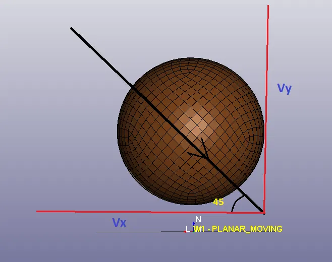
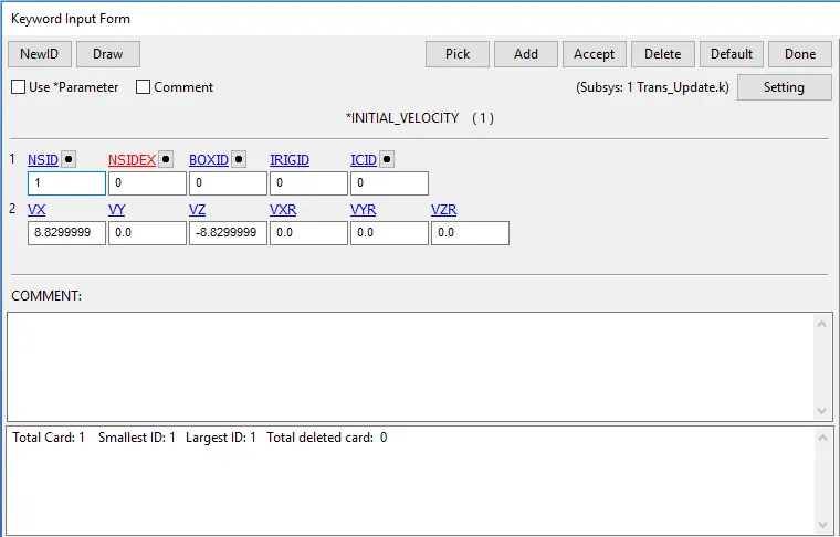
Velocity component of
`Vx = V cos theta`
`Vy = V sin theta`
the considered velocity of impact is 45km/hr, therefore as per the unit system, it will be 12.5 mm/ms.
Therefore, Vx = 8.82
Vy = 8.82 (-ve dit=rection indicates the reverse direction)
6)Control and Database card
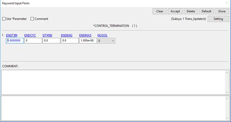
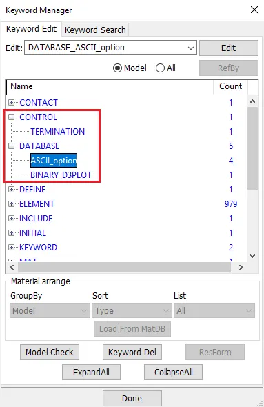
The last step was defining the appropriate control and database cards like Termination, Output request like ASCII, Binary D3plot, ELEOUT, etc.
CASE2:- The head impact with the rigid
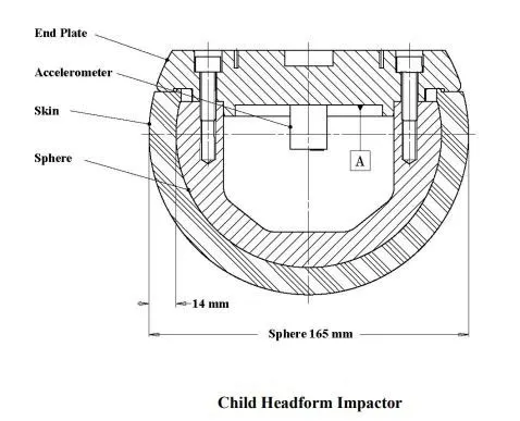
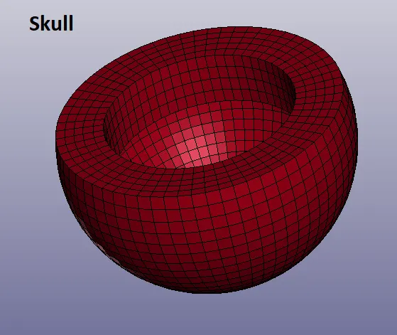
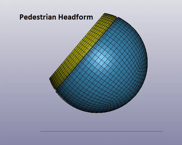
The Component Of a Child_Pedestrian_headform
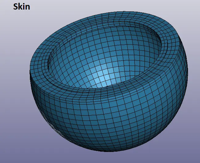
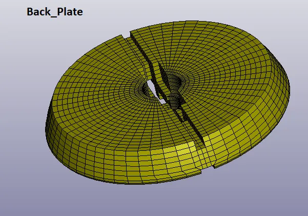
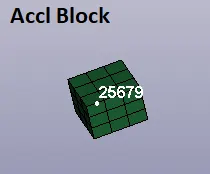
The entire procedure for the CASE will be the same the only difference is that the Ball file is replaced by the "Pedestrian_Headform" file, The angle of impact is taken as 50 degrees as per the AIS 100 and the speed is taken as 35 km/Hr i.e. 9.7 mm/ms.
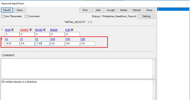
Boundary Condition
The Velocity I have considered here is 35km/hr i.e. 9.7 mm/ms and its component be,
Vx = 6.23 mm/ms
Vy = 7.43 mm/ms
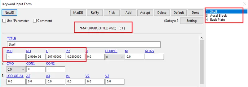
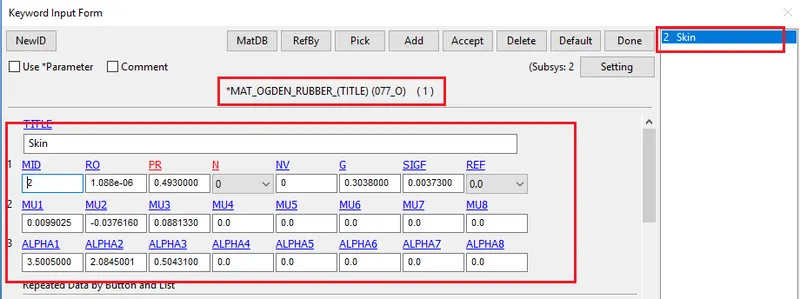
Material Cards
In the actual scenario, the Skull is more rigid than the outer muscles and skin therefore while defining, material defined over the Skull, Accel Block, and Backplate were MAT_RIGID.
While on the Skull was defined by MAT_OGDEN_RUBBER material. (Material data is taken from the AIS 100 std only)
for section Solid section with Element formulation, 1 was used.
The Contact Definition:
Contacts are necessary to define the actual behavior of the bodies during the impact.
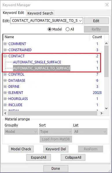
Two contacts defined in the problem
1) Automatic Surface to surface between the Skull and the Skin, where Skull was defined as Master and the Skin was defined as the Slave.
2) Automatic Single surface between the Headform skin and the Rigid Wall, where Rigid wall was a Master and the Skin of head form as Slave.
Constrained Definition
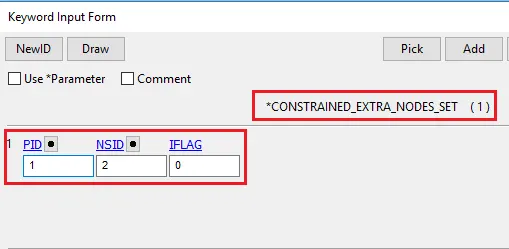

Constrained Extra node-set card used to Define Extra node over the Skull Body
Constrained Rigid Bodies used to Merged Two rigid bodies in our case these bodies are Skull (Master) and Back-Plate (Slave).
-Finally all case Setup I had Run the simulation
CASE3:- The impact simulation of the head form with the Hood
CASE3 set up is Totally the same as CASE 2, the only difference is we opened the hood file first and used *INCLUDE card to include the CASE 2 File in the CASE3 setup.
Also, the Rigid wall has replaced by the Hood model.
Material and Section Definition.
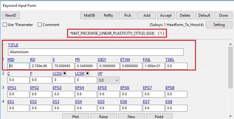
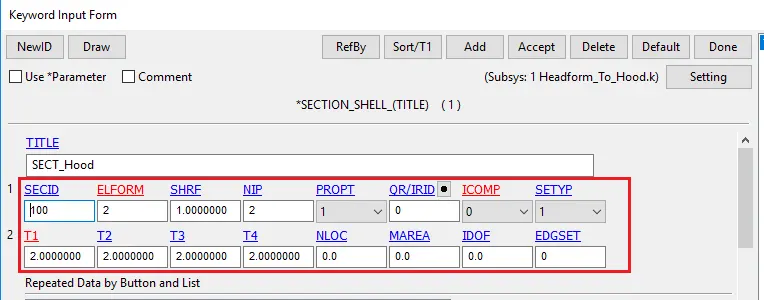
As For Headform, the material is predefined, so applied the Material of MAT_Piecewise_Linear_Elastisity_ Aluminium. for Section define 2mm thickness over the Hood shell elements.
Contract Definition
Define the Automatic Surface to surface between the Skin and Hood, where Skin was defined as Master and the Hood was defined as the Slave.
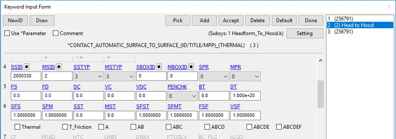
All other Boundary Conditions and constraints are the same.
Except for CASE1, All The simulations run on 30ms Termination time so it's easy to compare the results.
PRE-PROCESSING
Animation REsults For VMS
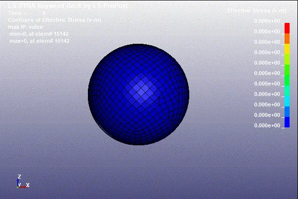
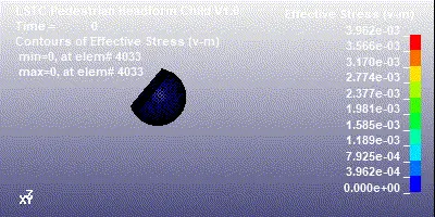
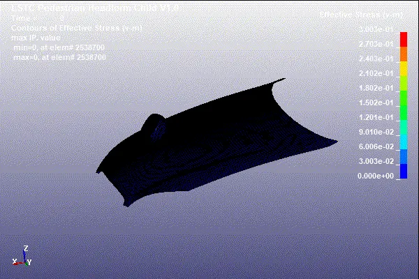
From the animation results, we can visualize how headform behaves in each case. In CASE1 it bounces back and after initial deformation, it regains its shape its due to the elastic material we have used. In CASE2 headform deform very badly and even after losing contact with the rigid wall it didn't regain its shape as it behaves like an actual headform collision over the rigid surface and deform plastically. In case 3 the hood deform to absorb the collision energy, there is little bet deformation & stress over the head for too but its not severe as compare to case2.
VMS Stress
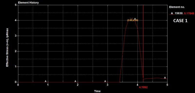
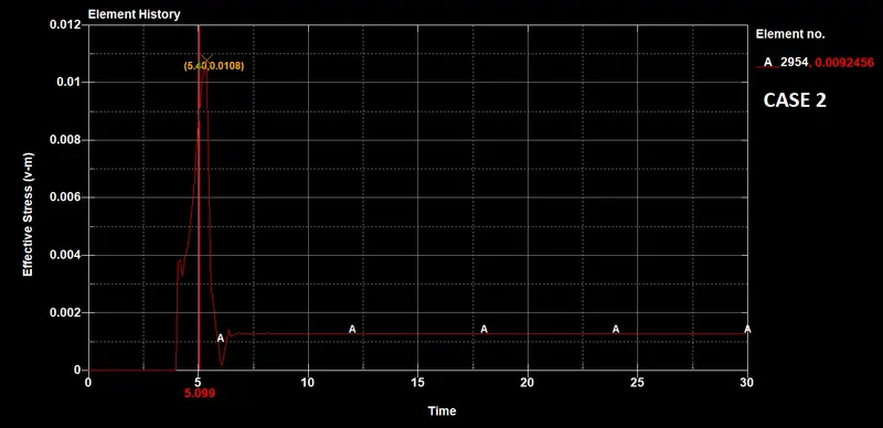
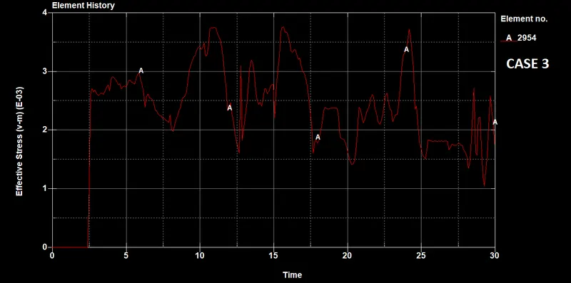
In case 1 the highest stress noted is 4.09Gpa, its irrelevant to compare this stress value with the other two cases as the material assumed for the ball is an Elastic one.
If we compare case2 and case3. In case2 Headform is impacted on the Rigid wall at the point of contact its experiences max stress of 0.0010Gpa and bounces back but due to headform absorbed the impact by deforming we are not seeing any impact stresses after approx 6th ms. This is because the wave traveled and absorbed by headform.
In case the deformable body is the Hood, this Headform Is more rigid than the Hood. We are getting the stress values over time as the headform is in contact with the Hood as it deformed to absorb the impact energy. Therefore er are getting such fluctuation in stress values.
Effective Plastic Strain
There is 0 Plastic strain in CASE 1 As the material deployed to the ball is an elastic one.
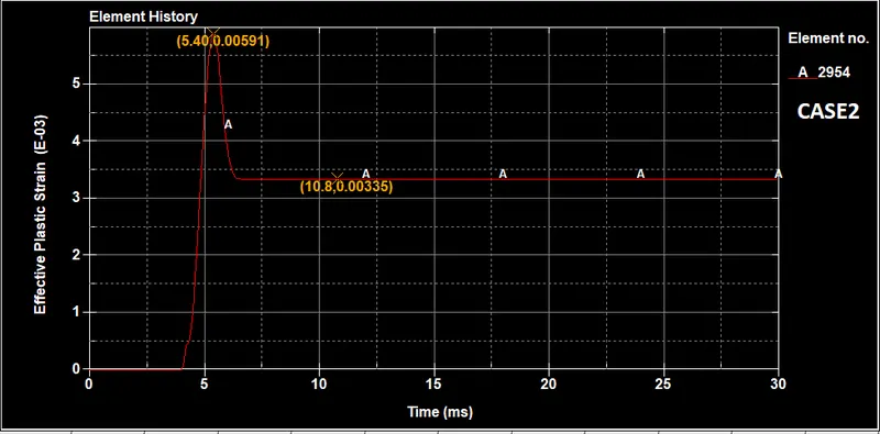
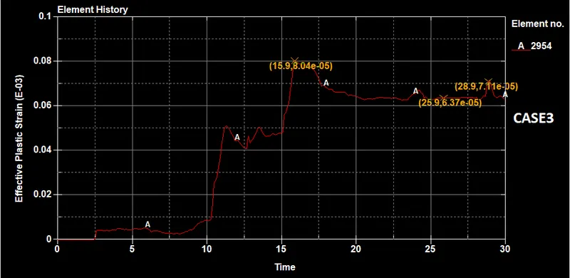
In case2 we can notice the large and Sudden deformation which is predictable, as it impacted on the Rigid wall. The max plastic strain noted was 0.0059 and then become constant at a value of 0.0033. After 6th ms, it becomes constant to the value of 0.0033 which indicates that the headform tries to achieve its original shape after the larger strain and settle down to 0.0033, which is in our case the result of permanent Plastic deformation.
In case 3 we can notice the strain increasing slowly over time, This is because the Hood deforms to minimize the impact by absorbing energy that is why the headform deformation is ay lower which is a good sign. This observation indicates that's the Hood will deform in such a situation (Real scenario) so the head form will be safe from the large deformation i.e. damage. The deformation is the power of -5 which is way lower than the case2.
Acceleration Plot
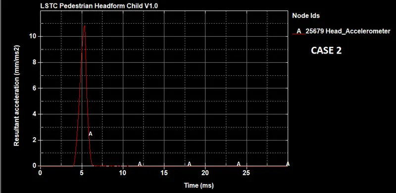
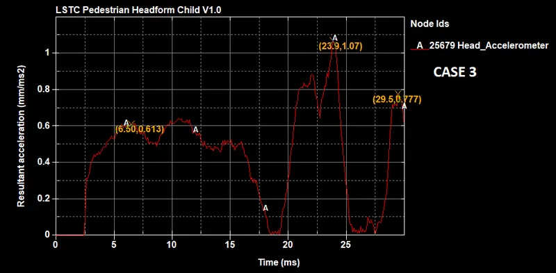
The Max acceleration noted in case2 was 10.9 mm/ms2 approx, which went down as soon as headform separated from the rigid body after impact. while in case 3 the Headform is in contact with the hood for all time being. That's why we can see the fluctuating acceleration value. the max value noted is 1.07 mm/ms2 which is way lesser than the CASE2. This is due to the Energy change between the Hood and the Headform.
Energy Graph
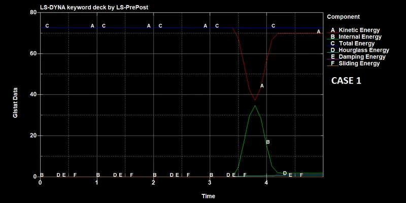
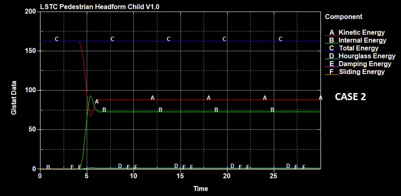
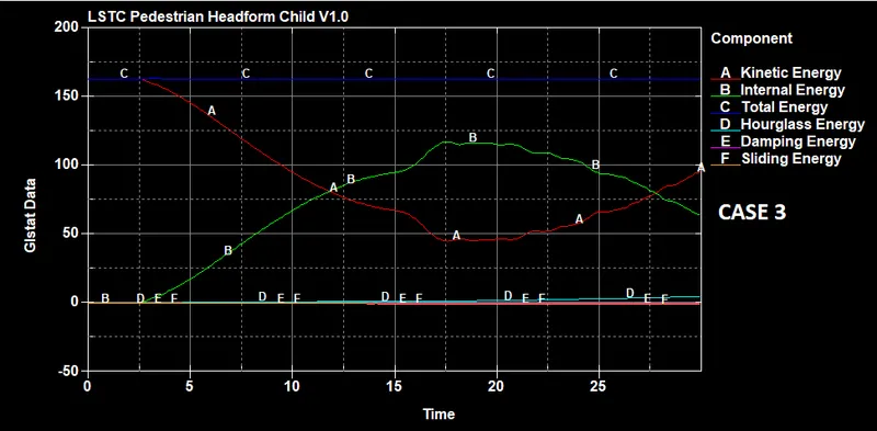
By examining the energy plot we can conclude that all the simulations are pretty stable especially the 3rd one as the totalEnergy has remained constant in the system. KE and IE behaving as they should be. A little Hoyrglass effect can be noticed at the end in 3rd CASE but it's acceptable as long as it remains in limit and didn't affect simulation or system results.
HIC Calculation
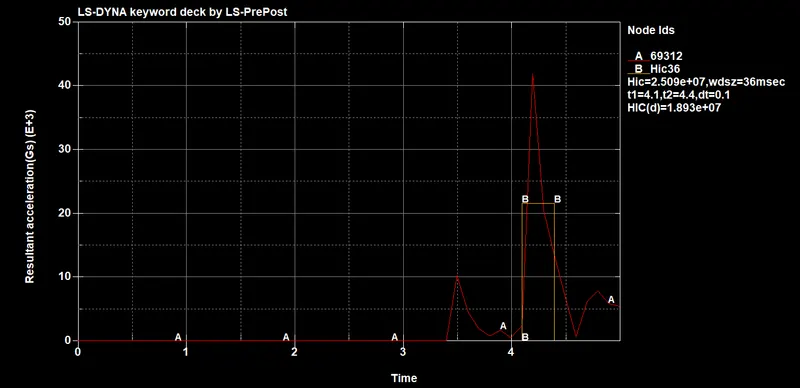
The HIC value here is enormously high due to the material property of a sample headform. This is not plotting real-world results by any means. For better evaluation o real-world scenarios CASE2 and 3 are Ideal.
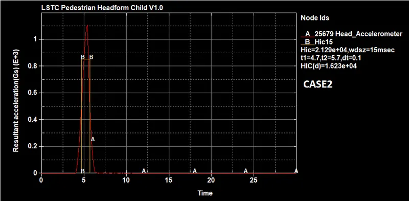
The Head impact Criteria is the criteria that determine the severity of the injury by calculating Avg. Acceleration and multiply with the Time difference. There is special Eq is there to Satisfy the HIC,
`HIC= max_(t1,t2) [1/(t2-t1) int_(t1)^(t2). a(t)dt]^2.5* (t2-t1)`
AVg Accelaration = 854
HIC= `(854)^2.5*(5.70-4.70)`
= 21312
Which is approximately same as we are getting from the Graph
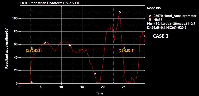
The Head impact Criteria is the criteria that determine the severity of the injury by calculating Avg. Acceleration and multiply with the Time difference. There is special Eq is there to Satisfy the HIC,
`HIC= max_(t1,t2) [1/(t2-t1) int_(t1)^(t2). a(t)dt]^2.5* (t2-t1)`
Avg Acceleration = 53.6
HIC= `(53.6)^2.5*(25-2.7)`
= 469
This is the same as we are getting from the Graph
CONCLUSION
-The HIC value here is enormously high due to the material property of a sample headform. This is not plotting real-world results by any means. For better evaluation o real-world scenarios CASE2 and 3 are Ideal.
- In CASE2 the HIC value is very High, Due to the headform Impact is held against the Rigid wall. In this, the Headform is the only one taking impact that's why we are seeing huge Deformation and which leads to this High HIC value. Head Injury of this level is very Severe for pedestrians especially child Pedestrians. that's why the hood of a car is made up of Deformable material.
- In CASE3 the HIC value is very lower as compared to the te CASE2 which is a good Indication. It's showing that Hood deformed according to its design and absorbed a larger amount of Energy which lead to a lower HIC value and eventually a less Severe head injury to the Pedestrian.
- That's why the hood of a car is made up of Deformable material. So it can be deformed by absorbing the Impact Energy and save pedestrians from Head Injury Risk. And Hood in CASE3 is passing the test as it's doing well during Pedestrian impact. (Result might not be accurate as only consider top shell of a hood)