Week-7 Head Impact
Introduction
Head injury remains one of the most frequent and severe injuries sustained by vehicle occupants, motorcyclists, pedestrians and cyclists in road accidents. One essential requirement for reducing the incidence of fatal and severe head injuries is to develop head injury assessment methods that can accurately and comprehensively assess the potential head injury risk under a broad range of head impact conditions. At present, the most widely accepted method of assessing head injury risk in road safety research is the Head Injury Criterion (HIC). These tests are performed with a lower velocity in a range of 20-40Kmph.
Objective
To perform head impact simulation for the different cases and derive the following results.
- The impact simulation of a simple head impact with the Rigid wall.
- The impact simulation of the Headform provided with the Rigid wall with the Stress / Strain plots and acceleration plot.
- The impact simulation of the head form with the Hood with the Stress / Strain plots and acceleration plot.
- The Stress / Strain plot from the Rigidwall simulation should be compared with the Stress / Strain plot from the Hood Simulation.
Procedure
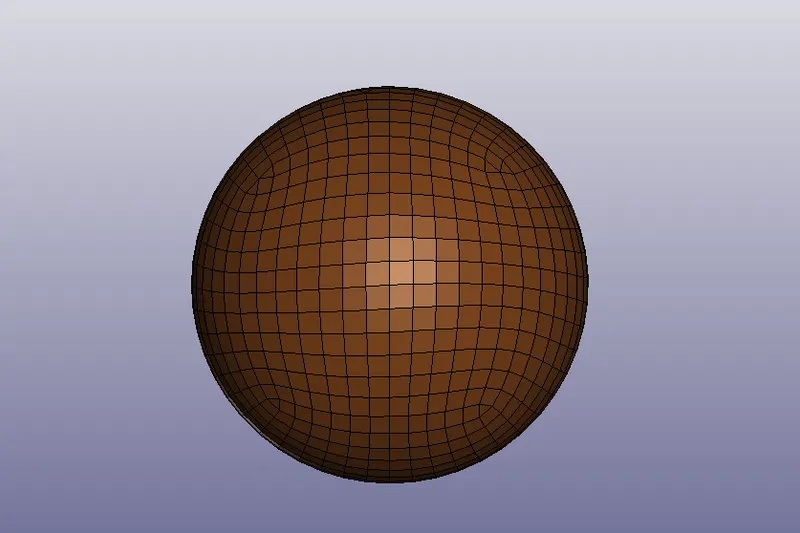
Case 1: Simple head impact on the rigid wall
- The given model is imported onto the workpage of the LS-Pre-post using File>Open>LS DYNA Keyword file.
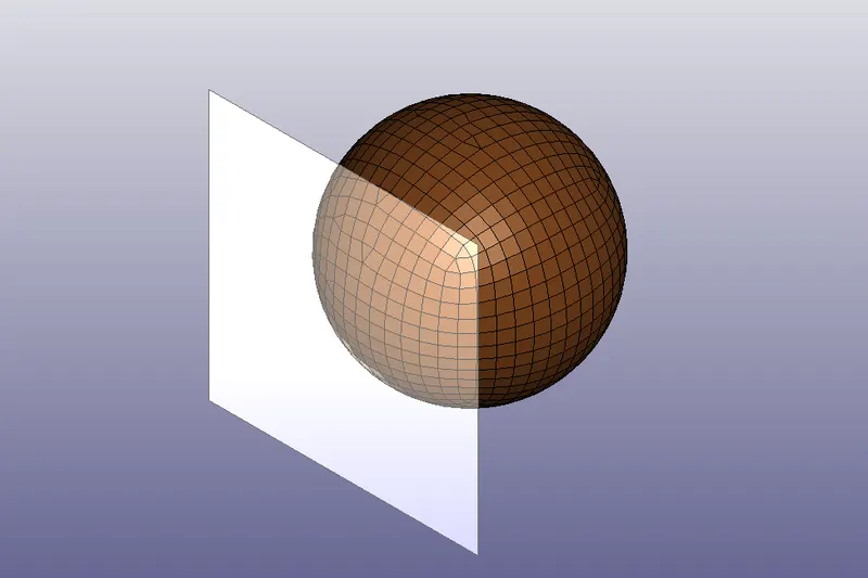
Creating a Rigid wall
- The given model does not contain any rigid wall needed for the analysis. A new rigid wall is been created using Create Entity> Rigid Wall.
- Here a planar wall is created by defining a vector with one point and a normal. The rigid wall is then offseted to a distance of 10mm from the bracket.
- It should be noted that the normal created by the rigid wall and the velocity of the brackets should be in an opposite direction. If its been in the same direction the bracket gets penetrated through the wall resulting a wrong simulation.
- Since the generated rigid wall and direction of velocity were in same direction, The normal is made opposite to each other by using the rotate command and specifying the angle and axis its to be aligned.
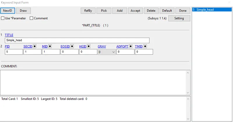
Assigning material and section to the brackets
- Materials can be classified as elastic materials, elastic plastic materials, hyper elastic materials, viscoelastic materials etc, in which metals and plastics can be modelled using elastic plastic material and is assigned using *MAT_024 (PIECEWISE_LINEAR_PLASTICITY) card from the keyword manager. If failure mode is highly complex or the material is a polymer, composite, thermoplastic, then *MAT_187 card can be used.
- Here a simple elastic property material property was assigned using *MAT_ELASTIC card.
- A section id with shell card is created for the part with (ELFORM=2) using Keyword manager>All>Section>Shell and a thickness of 1mm is assigined.
- Now these created material id and section id are assigned to the part using the part option under keyword manager.
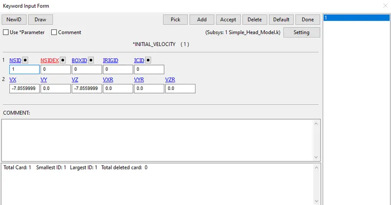
Assigning velocity to the part
- Before assigning the velocity to the the head part, a node set containing all the nodes of the head has to be created. This can be done using create entity option or by set option under keyword manager.
- Here we have assumed that the head model has been moved along the path with a velocity of 40kmph along z-axis. This value has been converted to the required unit system and resolving it into x and z direction at an angle of 45 degree. Therefore a velocity of -7.855mm/ms have been assigned along x and z direction thus gives the resultant velocity along the required direction.
Giving contact definition
- Contact in LS DYNA is defined using contact surfaces and occurs when one surface of the outer surface of a model penetrates another segment.
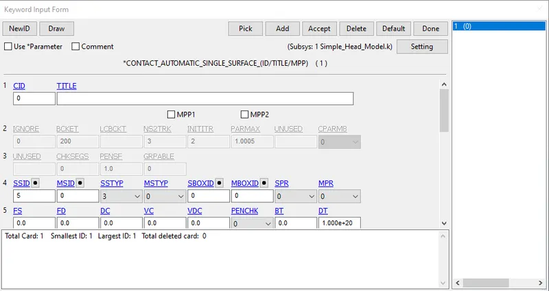
- Here an *AUTOMATIC_SINGLE_SURFACE card from keyword manager is been used and Slave segment set ID (SSID) is assigned to the part set containing both the parts of bracket and leaving the MSID blank.
Assigning termination time
- *CONTROL_TERMINATION_CARD from keyword manager is used to define the simulation time using ENDTIME otpion.
- Here an ENDTIME of 4ms was assigned to the termination card. (Additional time after the impact is added to get the crash, bouncing, buckling effect etc).
Database
- The oputput data needed for the analysis is generated using *DATABASE card.
- DATABASE_BINARY_D3PLOT under keyword manager ensures d3plot files are written in which it stores the stress strain contours of the deformed system.
- ASCII under keyword manager can generate different output such as force generated in a contact, total energy, material engery etc. Here output for ELOUT, GLSTAT, MATSUM, RCFORCE, NODOUT, SLEOUT,SWFORCE are been requested.
- HIC value is been extracted using NODEOUT in*DATABASE_HISTORY_NODE card. Here a bottom most node with hits the wall has been selected in order to extract the result.
Model check up and running the simulation
- The model is checked for any errors and if any error occurs it should be corrected further.
- The .k file is been saved and runned using LS-DYNA manager.
- If Normal termination is showed after running the file, its then ready to do post processing.
Case 2: Headform model impact on rigid wall
Rotating the head model
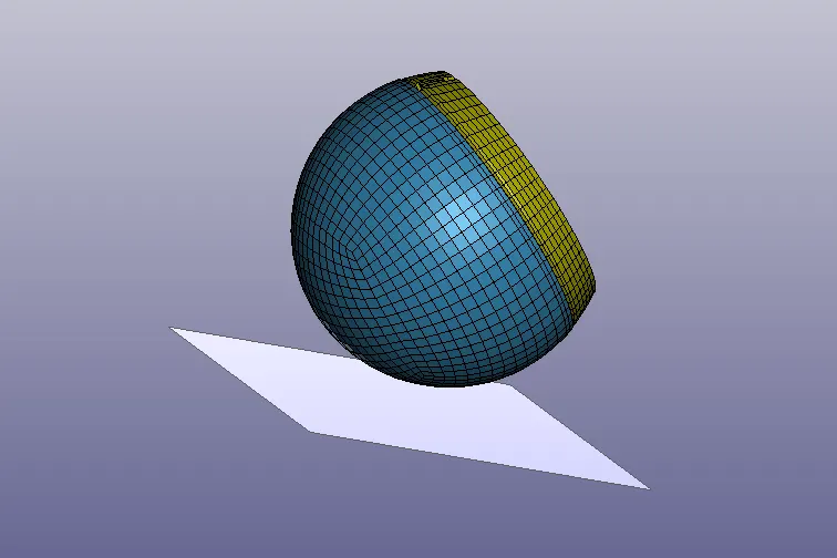
- Here the model resembles to a child's head. So the impact of the head to the rigid wall is considered to happen at an angle of 45 degree. Since the model that used for the case 1 was a circular one, it not necessary to rotate the model along required axis. But here the model is not perfectly circular it been rotated along the particular axis.
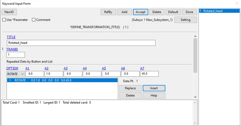
- For that a new Ls-prepost was opened and a *DEFINE_TRANSFORMATION card was opened from the keyword manager and the required required directional vectors and angle were assigned here.
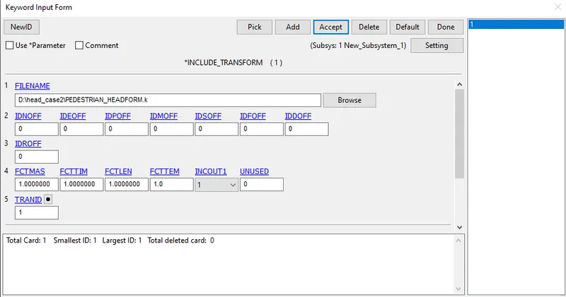
- *INCLUDE_TRANSFORM card was used to complete the roation procedure by priscribing the TRANSID from the card and browsing the required file to transform.
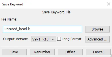
- Now save the file by using "save keyword as" and save it with some file name.
- The saved model is again opened onto the work page of Ls prepost.
For this case also same procedure was followed as that of case 1 to create a rigid wall, Assigning the velocity, defining the contact definition.
Assigning termination time
- *CONTROL_TERMINATION_CARD from keyword manager is used to define the simulation time using ENDTIME otpion.
- Here an ENDTIME of 5ms was assigned to the termination card. (Additional time after the impact is added to get the crash, bouncing, buckling effect etc).
Database
- The oputput data needed for the analysis is generated using *DATABASE card.
- DATABASE_BINARY_D3PLOT under keyword manager ensures d3plot files are written in which it stores the stress strain contours of the deformed system.
- ASCII under keyword manager can generate different output such as force generated in a contact, total energy, material engery etc. Here output for ELOUT, GLSTAT, MATSUM, RCFORCE, NODOUT, SLEOUT,SWFORCE are been requested.
- HIC value is been extracted using NODEOUT in*DATABASE_HISTORY_NODE card. Here a bottom most node with hits the wall has been selected in order to extract the result.
Model check up and running the simulation
- The model is checked for any errors and if any error occurs it should be corrected further.
- The .k file is been saved and runned using LS-DYNA manager.
- If Normal termination is showed after running the file, its then ready to do post processing.
Case 3: Headform model impact on hood
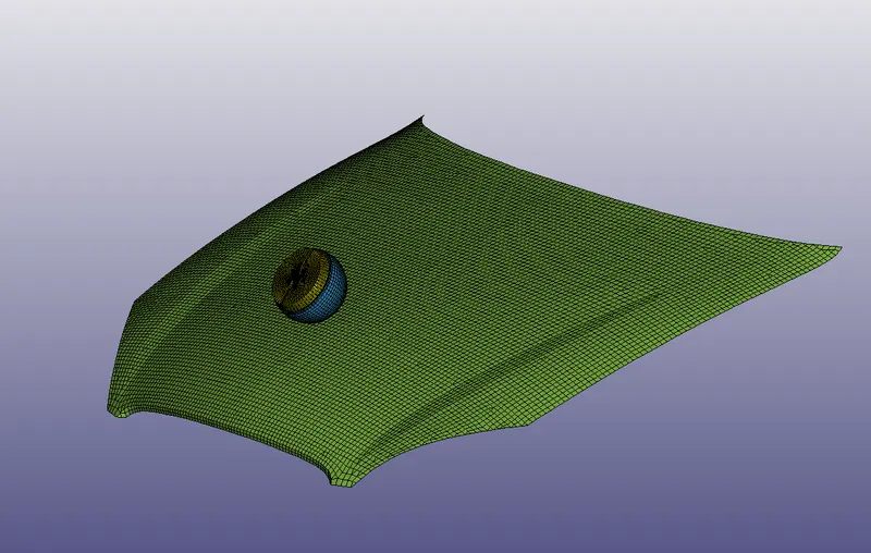
For this case the impact simulation were performed using a child's head and a hood model given and thereby making use of *INCLUDE card to do this simulation. A new folder was created with a suitable name and the .k file for the rotated head without rigid wall were copy pasted to the that folder, Also the .k file of the given hood model was pasted into the same folder as well.
Defining section and material to the hood part
- A new Ls-prepost was opened and the given hood model was imported onto the work page.
- A section id with shell card is created for the part with (ELFORM=2) using Keyword manager>All>Section>Shell and a thickness of 1.5mm is assigined.
- Elasto-plastic material card was used to define the material of the hood.
- Now these created material id and section id are assigned to the hood using the part option under keyword manager.
Including the rotated head file to the meshed hood model
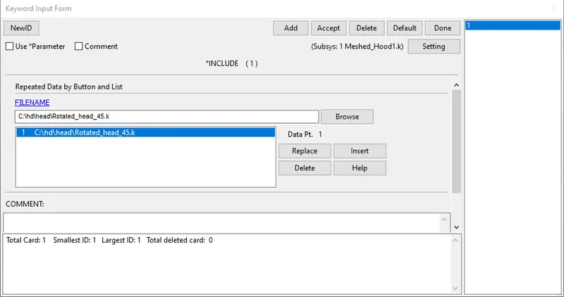
- After opening the hood model, *INCLUDE keyword was used to include the roated head model to the meshed hood file.
Defining contact
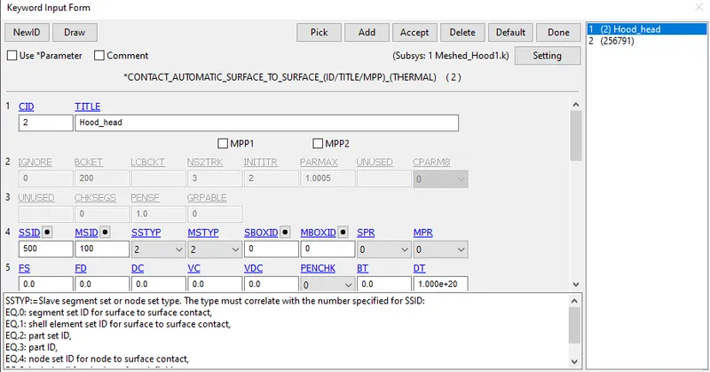
- Here a *AUTOMATIC_SURFACE_TO_SURFACE card was used to define the contact between the head and the hood part by considering the hood as the master segment and head as the slave segment.
Assigning velocity to the headform
- Before assigning the velocity to the the head part, a node set containing all the nodes of the head has to be created. This can be done using create entity option or by set option under keyword manager.
- Here we have assumed that the head model has been moved along the path with a velocity of 40kmph along z-axis. This value has been converted to the required unit system and resolving it into x and z direction at an angle of 45 degree. Therefore a velocity of -7.855mm/ms have been assigned along x and z direction thus gives the resultant velocity along the required direction.
Assigning termination time
- *CONTROL_TERMINATION_CARD from keyword manager is used to define the simulation time using ENDTIME otpion.
- Here an ENDTIME of 20ms was assigned to the termination card. (Additional time after the impact is added to get the crash, bouncing, buckling effect etc).
Database
- The oputput data needed for the analysis is generated using *DATABASE card.
- DATABASE_BINARY_D3PLOT under keyword manager ensures d3plot files are written in which it stores the stress strain contours of the deformed system.
- ASCII under keyword manager can generate different output such as force generated in a contact, total energy, material engery etc. Here output for ELOUT, GLSTAT, MATSUM, RCFORCE, NODOUT, SLEOUT,SWFORCE are been requested.
- HIC value is been extracted using NODEOUT in*DATABASE_HISTORY_NODE card. Here a bottom most node with hits the wall has been selected in order to extract the result.
Model check up and running the simulation
- The model is checked for any errors and if any error occurs it should be corrected further.
- The .k file is been saved and runned using LS-DYNA manager.
- If Normal termination is showed after running the file, its then ready to do post processing.
Results
The head impact simulation for the three cases were performed and the various parameters and stress strain plots, acceleration plots were discussed.
Von-mises stresses
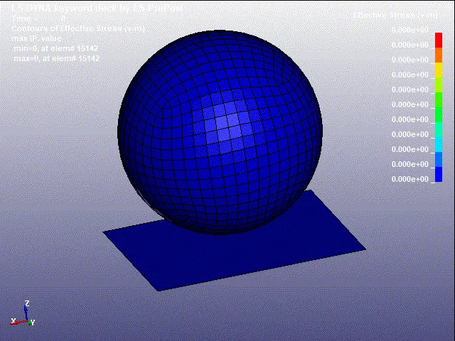
Case 1:
Case 2:
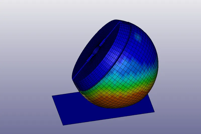
Case 3:
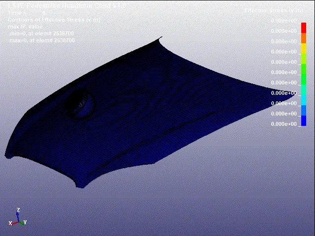
From the Von-mises plot it can be observed that the stress value reaches higher at the time of impact and decreses steadly. There is no much deformation observed in the simple head (case1) geometry. For the case 2 there is a deformation in head geometry and its due to the material properties assigned to the headform and for the case 3 there is deformation in head and hood geometry as well. The deformation were found to be maximum for hood because of being a lighter material, It tends to deform elastically till the yield point and then plastic deformation happens.
Effective plastic strain
Effective strain can be plotted using History>Element>Efective plastic strain.
Case 1:
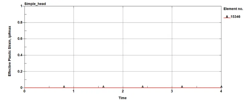
From the strain plots it's observed that the total strain value for case 1 is zero through out the process. Its due to the material properties assigned to the model. here the value of youngs modulus is very high, so no considerable deformation can be seen here.
Case 2:
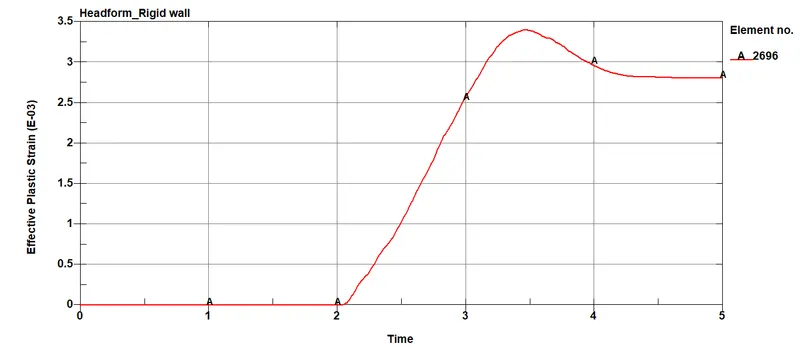
The above plot shows the effective strain for element 2695 during the impact of the headform with a rigid wall. The rigid wall is non-deformable and we can see deformation only for the headfrom model here. The plastic strain drops from 3.47ms and reaches a constant value and the constant value denotes the parmenent deformation in the headform model.
Case 3:
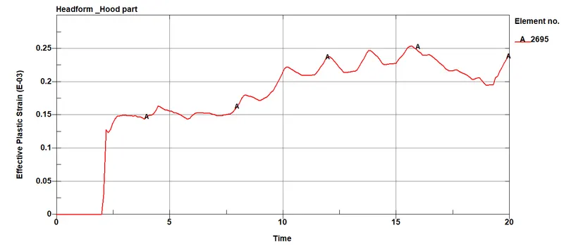
The above plot shows the effective plastic strain for the element 2695 during the impact of headform and the hood model. It's observed that the effective strain value for the case is less when compared with case 2. Its becaues the hood is modelled with an aluminium material which absorbs energy and tranfer less energy to the headform during the impact.
Energy plots
Case 1:
Case 2:
Case 3:
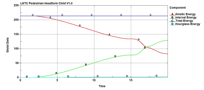
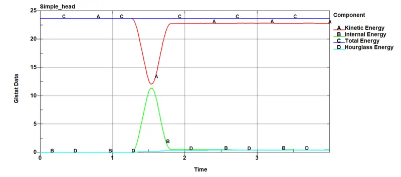
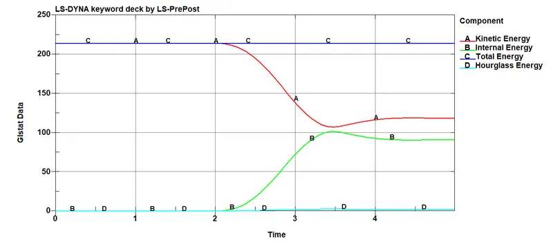
- From the energy plots it's been observed as the total energy for the case1 is very less when compared to case2 and case3. Its because of the elastic property of the material that have been used for the case1. For the other two cases the headform was modelled using hyper elestic material giving higher energy values.
- From the case1 its observed that the kinetic energy decreases and internal energy increases during the time of impact due to the reduction in velocity and bounce back minimum energy loss. For the case2, since the headform was modelled using hyper elastic material some energy is been absorbed due to the deformation happened during the impact and for the case3 we can see the internal energy increases gradually when compared to the other two cases. Its because of the usage of the hood model here where it also deforms during the impact which causes the decrease in the velocity of the headform.
- Even though there is a minute increase the hourglass energy for the cases, its been kept under the limit.
HIC 36 Plots
-
The head injury criterion (HIC) is a measure of the likelihood of head injury arising from an impact. The HIC can be used to assess safety related to vehicles, personal protective gear, and sport equipment.
Normally the variable is derived from the measurements of an accelerometer mounted at the center of mass of a crash test dummy’s head, when the dummy is exposed to crash forces.
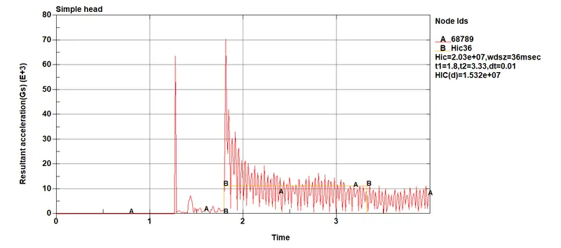
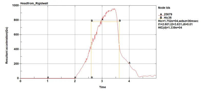
- The plots below shows the values for HIC 36 caluclated in Ls-dyna which measures for a time intervel less than 36ms.
Case1:
Case2:
Case3:
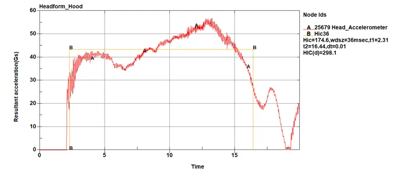
- From the plot it can be observed that the HIC for case1 is more when compared to other two cases. This is because that the head geometry in case1 dont deform much due to material properties causing less strain. For the case2, the HIC value is more when compared to case3 due to the impact of the headform with the rigid wall. In case3, a hood model was used for the impact with the headform which represent an actual scenario. Since the hood part also get deformed here after the impact the cause of head injury is very less fo this case.
Conclusion
- In this project, a head impact simulation were done step by step for different cases and finally performed a scenario where this headform will impact on a car bonnet. The head impact coefficient were also calculated manually with the help of LS-PrePost and compared the results.
............................................................................................................................................................................................................
File: https://drive.google.com/drive/folders/1HlzQHVMOizoMAWZkpnR79XNWtU6YX5v7?usp=sharing