Week-7 Head Impact
AIM: To perform the head impact simulation from a simple ball and rigid wall to head foam and Hood, check the stresses that are developed on the hood and head foam, also calculate the Head Injury Coefficient (HIC).
PROCEDURE:
CASE1:
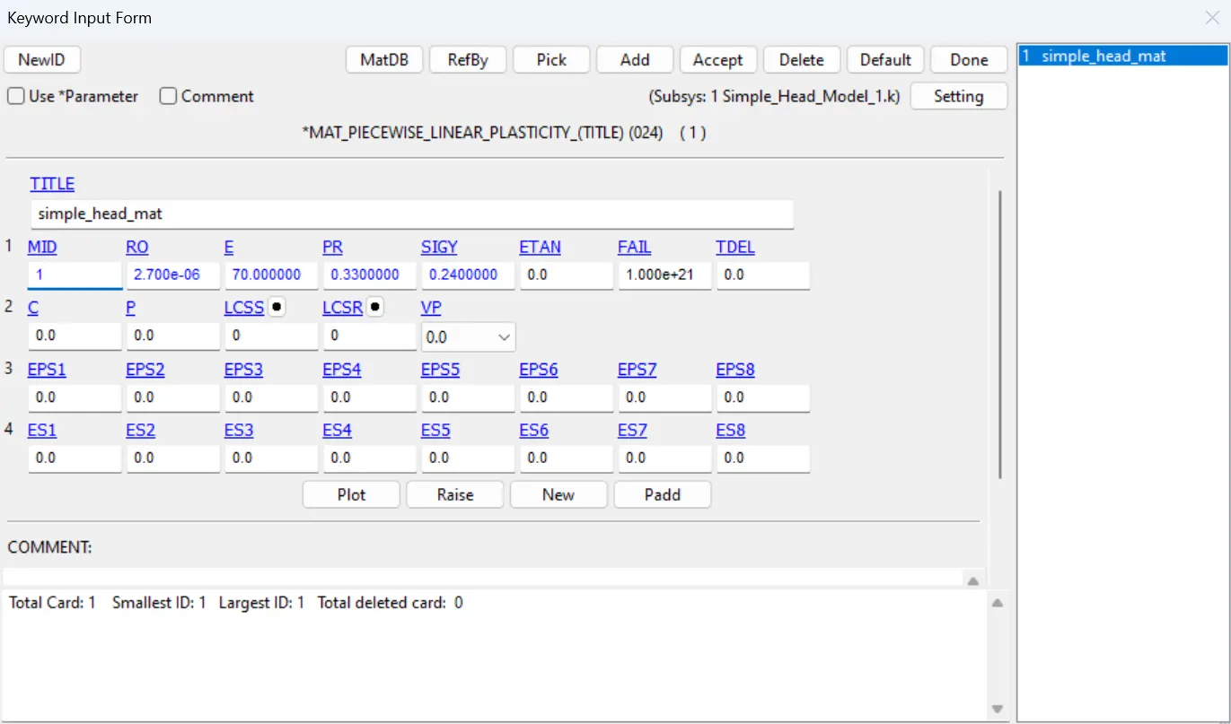
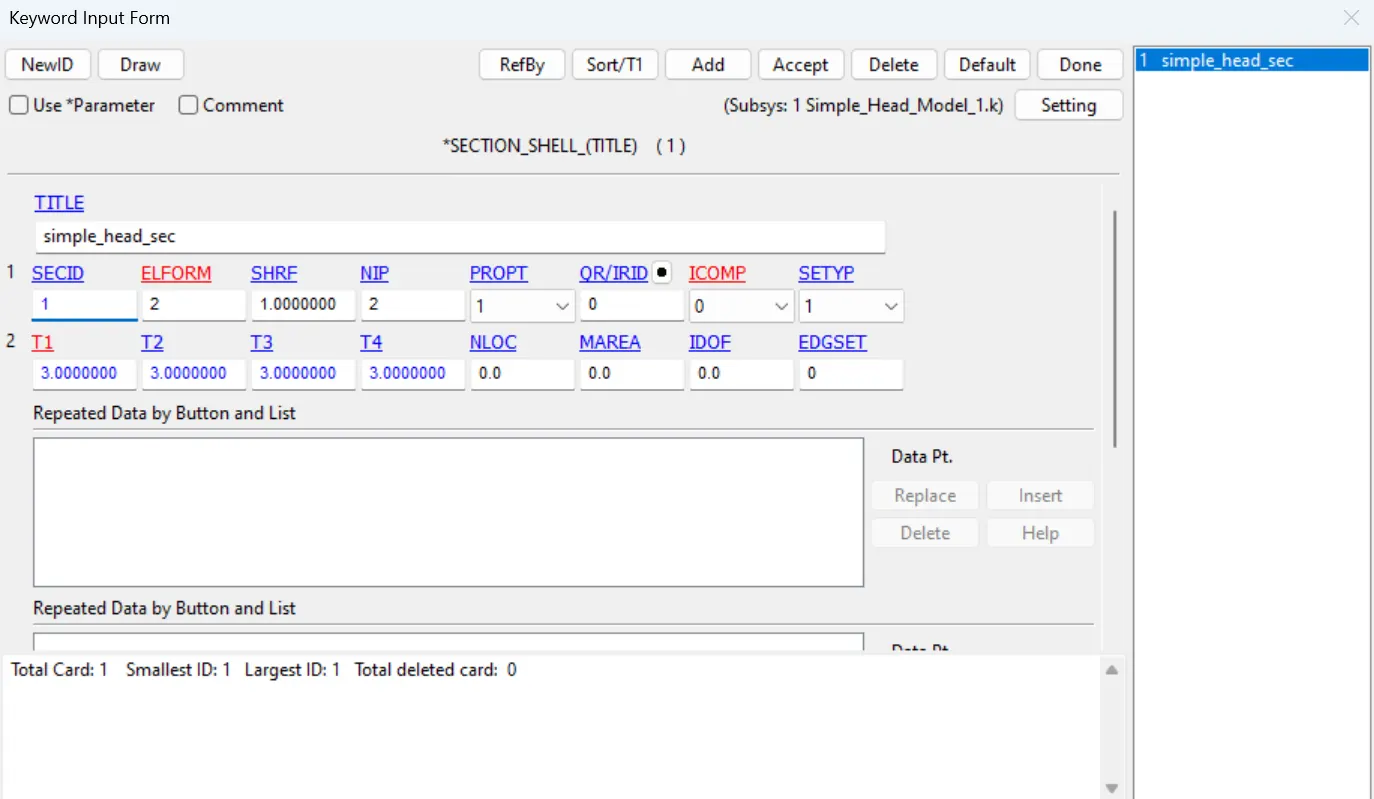
- First open the keyword file of simple head model and apply material properties as by selecting the MAT_024 PIECEWISE LINEAR PLASTICITY and section to be assigned with thickness of 1.5.
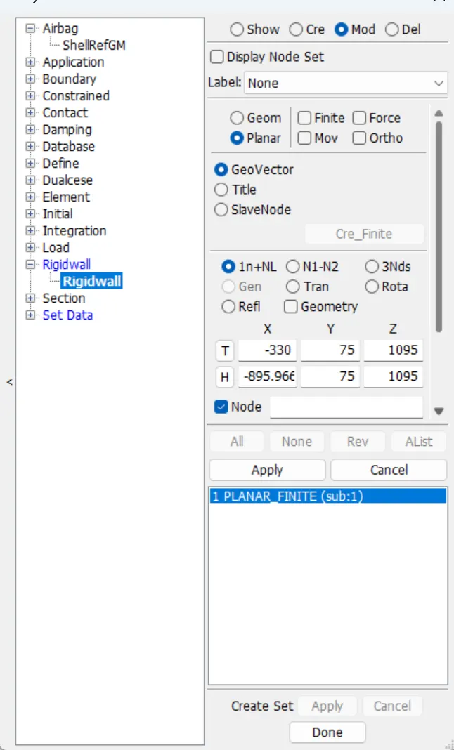
- Create the Rigid wall from create entity module along X direction with a distance of 15. Make sure that the rigid wall normal pointing towards the simple head model otherwise the it wil go through the rigid wall.
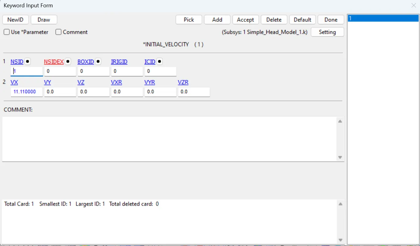
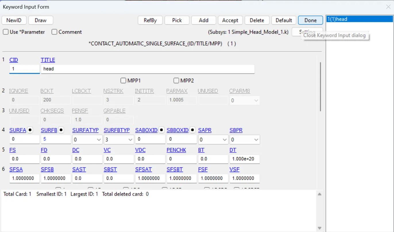
- Create the initial velocity keyword with 40KMPH (-11.11mm/ms) along the X direction. Then create the AUTOMATIC SINGLE SURFACE CONTACT to all the nodes of the simple head model
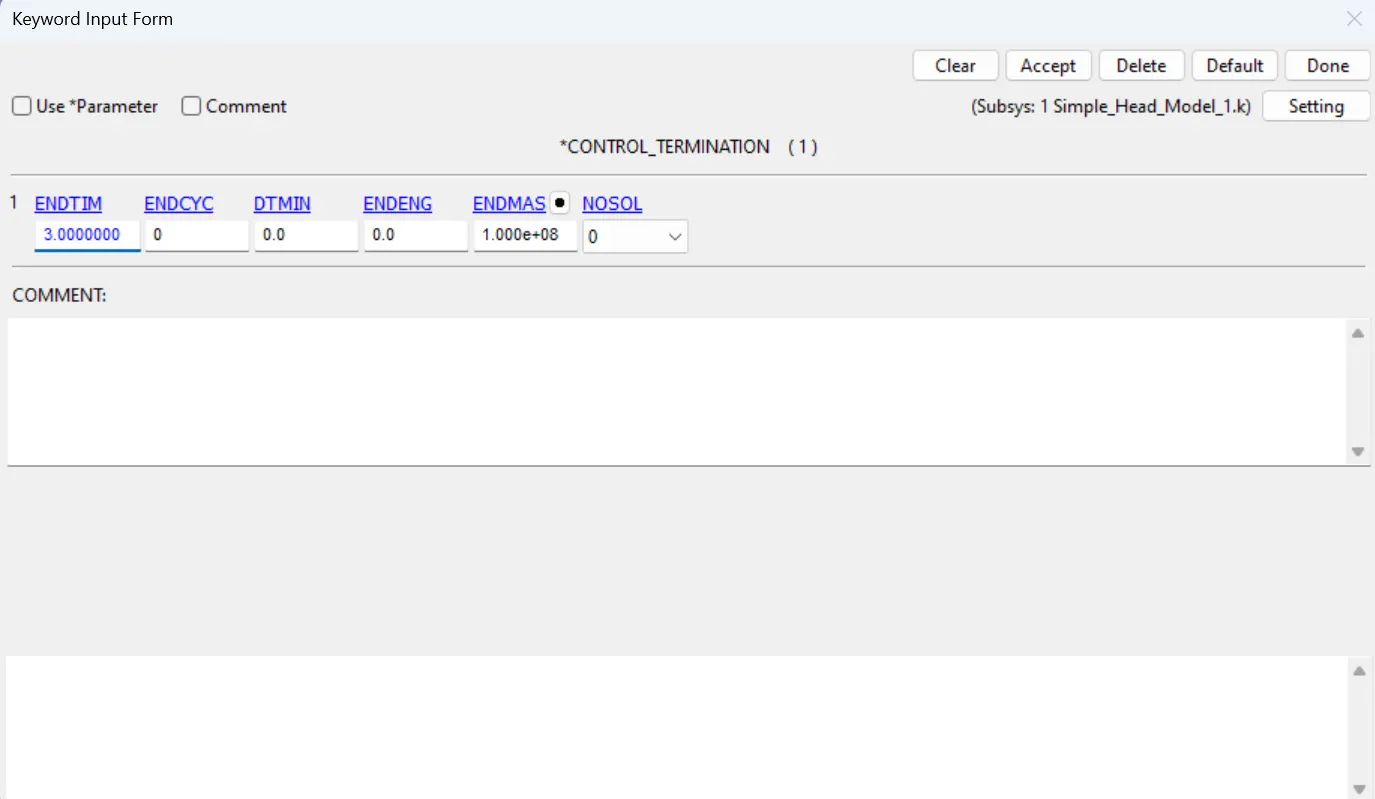
- Then give the CONTROL TERMINATION CARD with time as 3 ms, and in the DATABASE card ASCII and d3plot is selected with time interval as 0.1ms.
CASE2:
- Here in CASE2 the we need to create a respective folder and copy and paste the head foam into that.
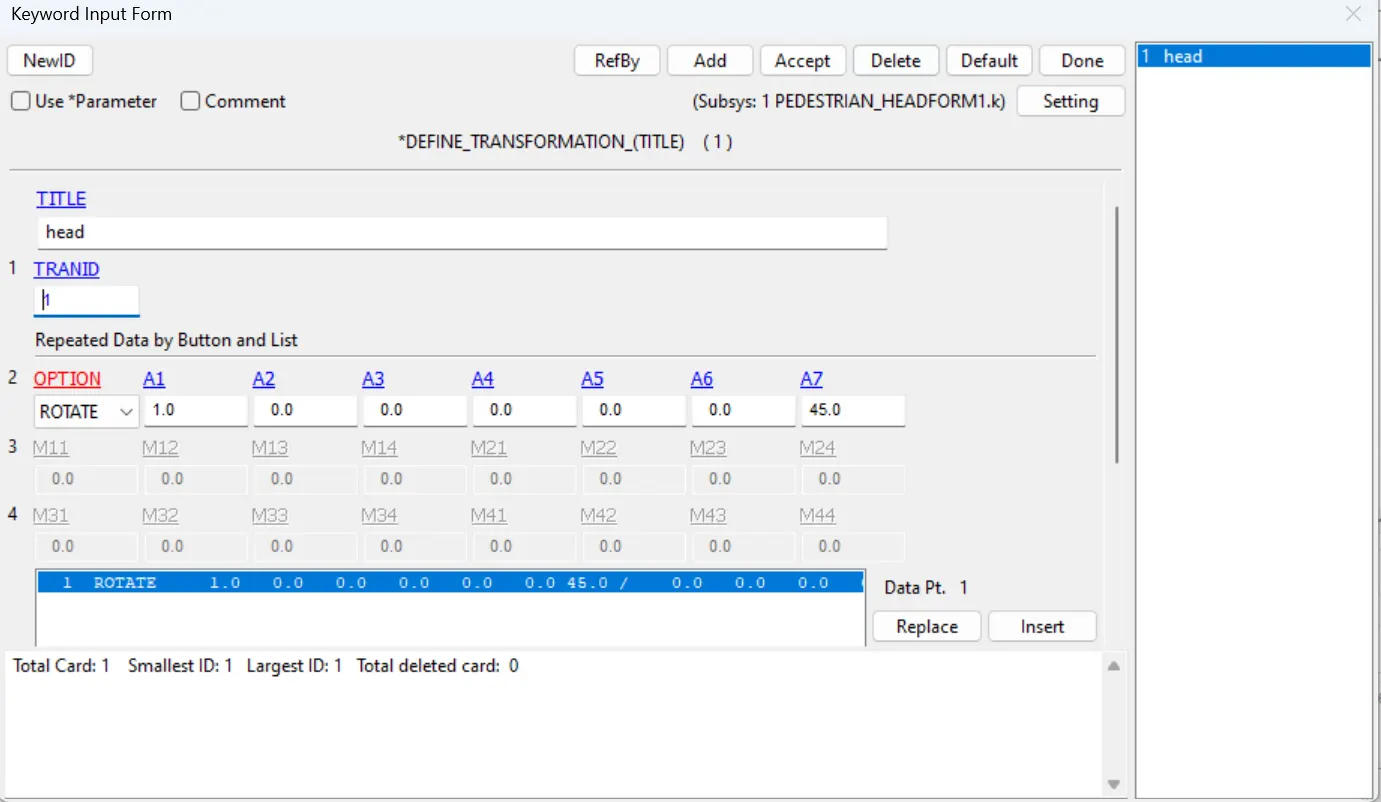
- Then open a new file and give the DEFINE TRANSFORMATION card to rotate along X direction 45deg as shown in the figure.
- Then use the INCLUDE_TRANSFORM keyword and select the head form file and trans ID as DEFINE_TRANSFORMATION ID.
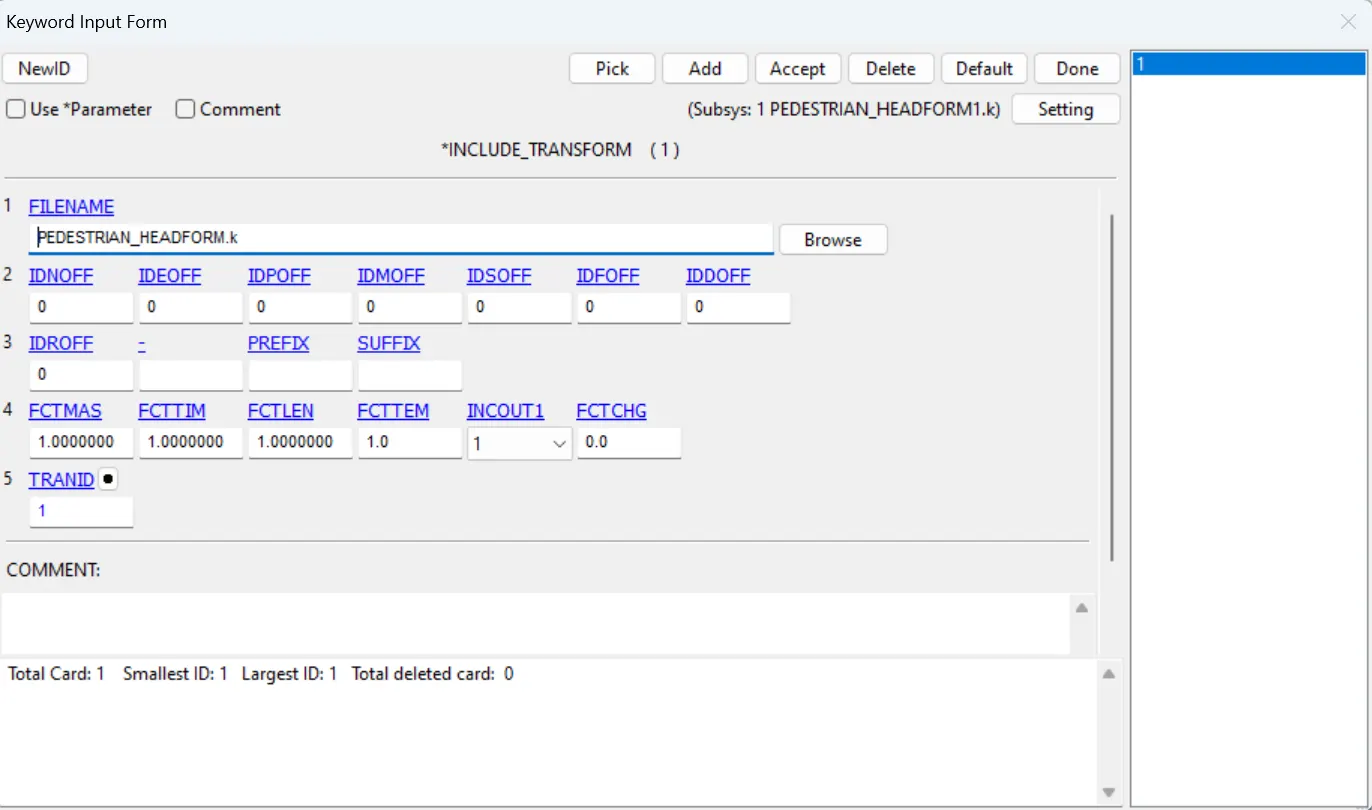
- Then this file in the same folder with different name, close the file and reopen the file.
- Then one can see the transformation of head foam is happened. Then create the rigid wall, initial velocity, Control termination, database cards are similar to case1.
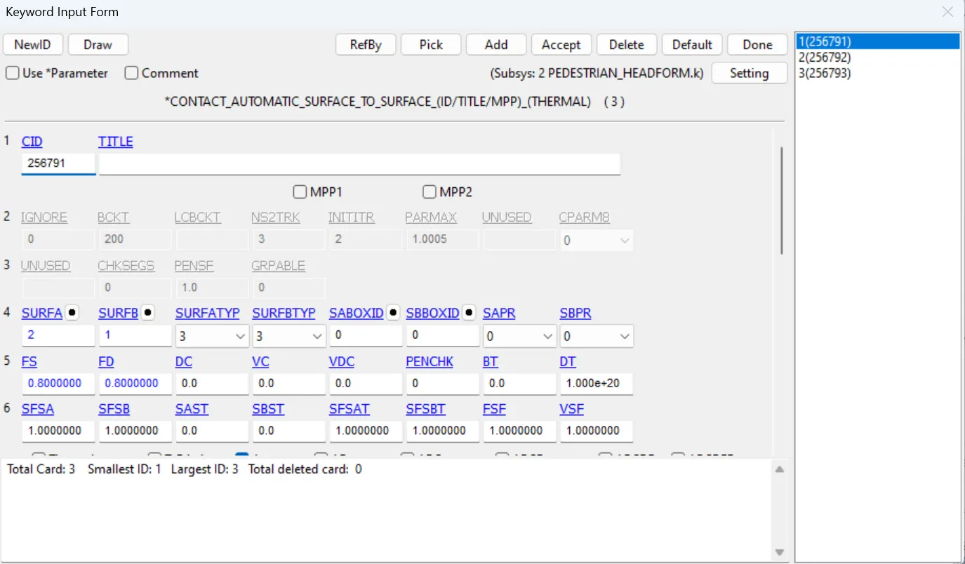
- The only change is that we need to introduce the CONTACT SURFACE TO SURFACE to Head foam parts.
CASE3:
- In case3 create a seperate folder for this as well and copy and paste the head foam file and meshed hood file into the folder.
- Now open a new file and Create the define transformation Y direction 45 deg, and use the include transformation card and save it as seperate file.
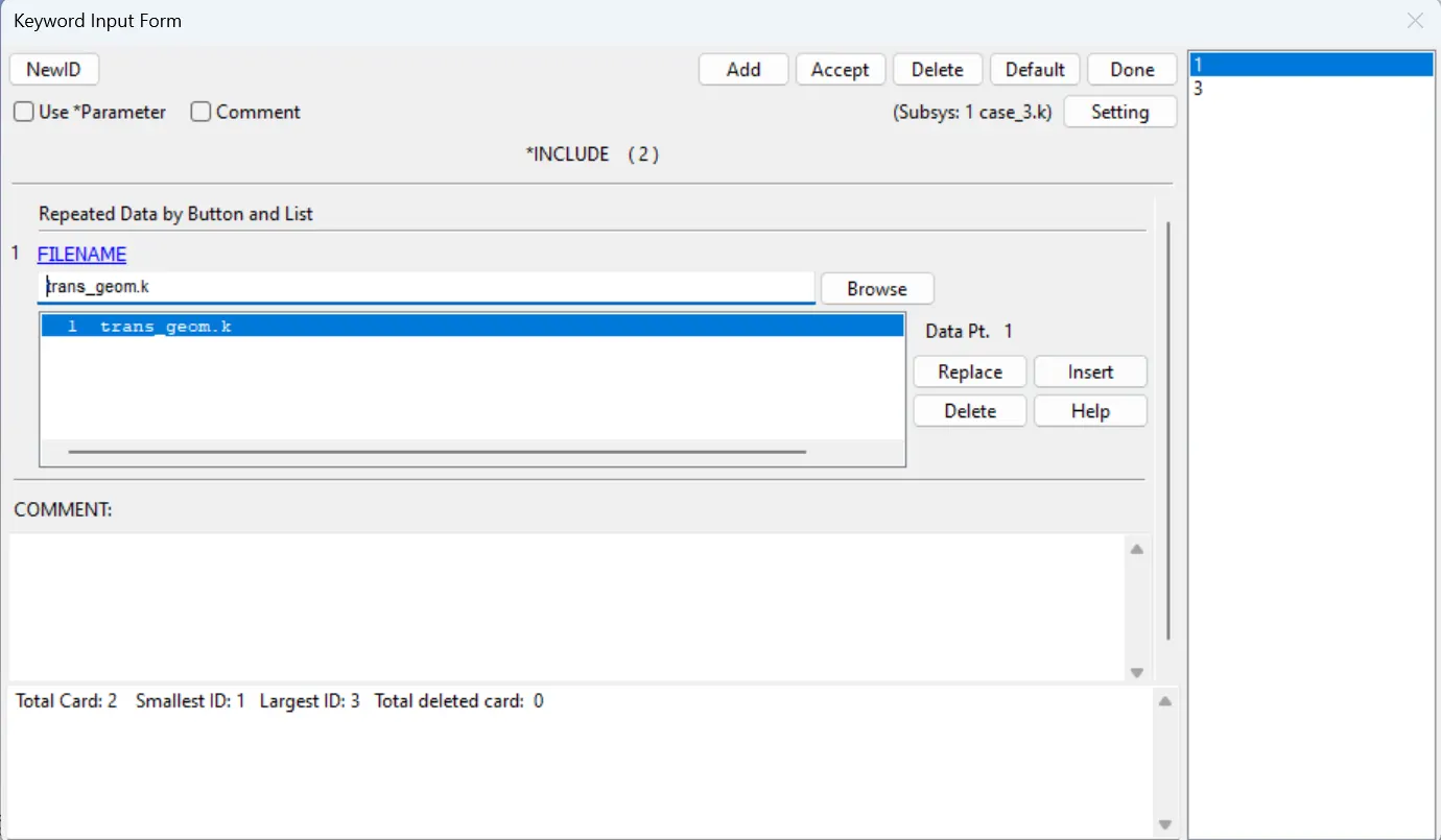
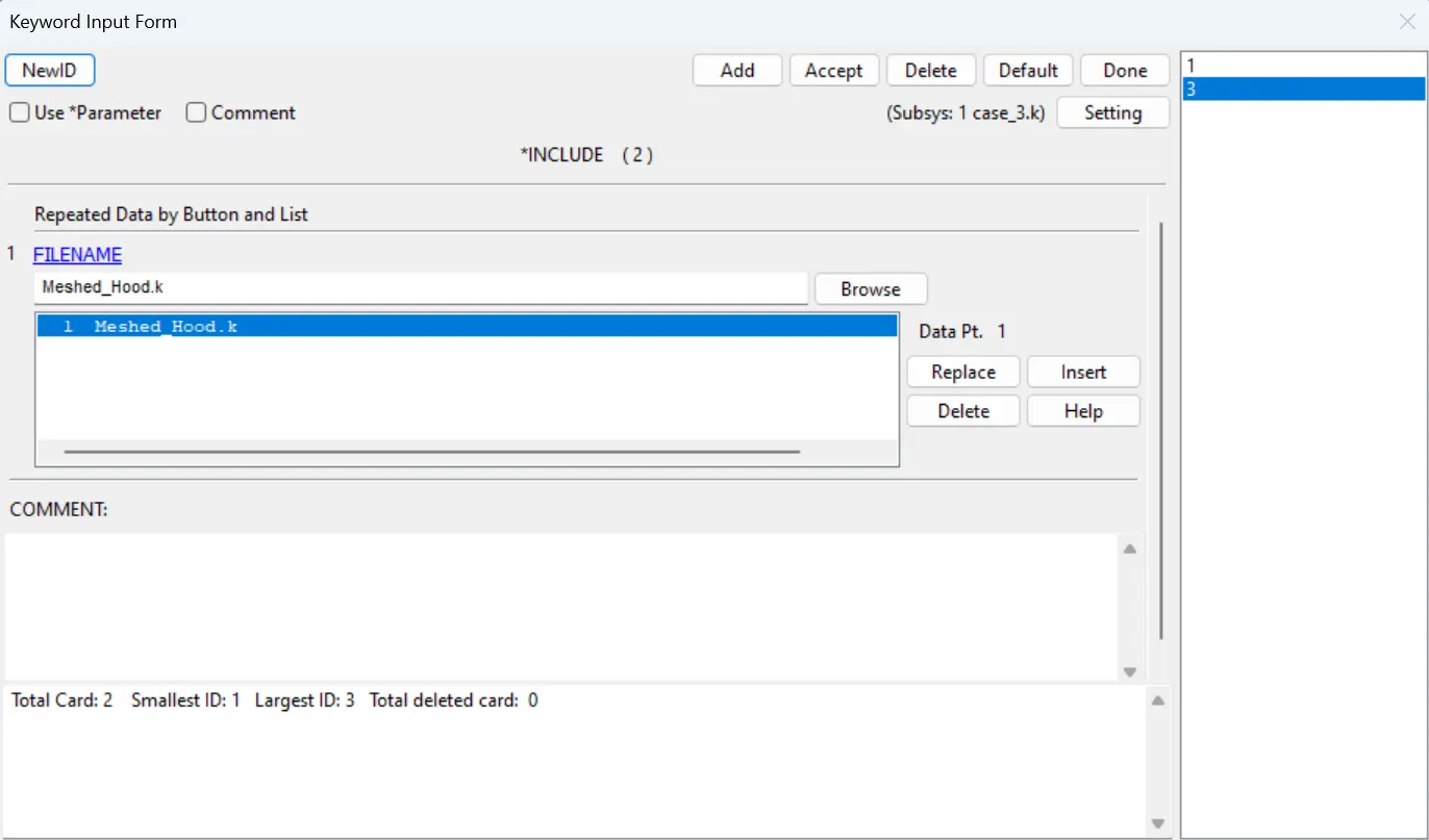
- Again open a new file and INCLUDE_INCLUDE to add the both new file which is created after transformation and meshed hood file.
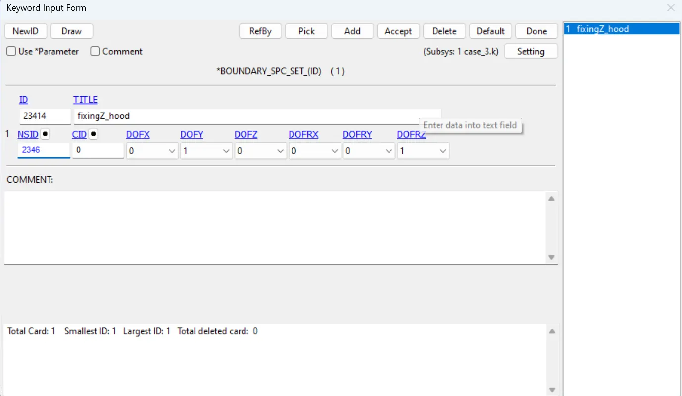
- Fix the perimeter points of the hood along Z DIR to restrict it while impact.
- The rermaining procedure is same as the case 2 like Contact, Initial velocity, control termination, Database files.
RESULTS:
The energy plots, vonmises stresses and HIC are shown in the figures below.
ENERGY PLOTS:
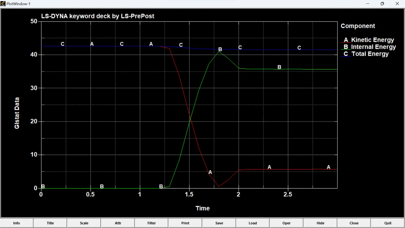
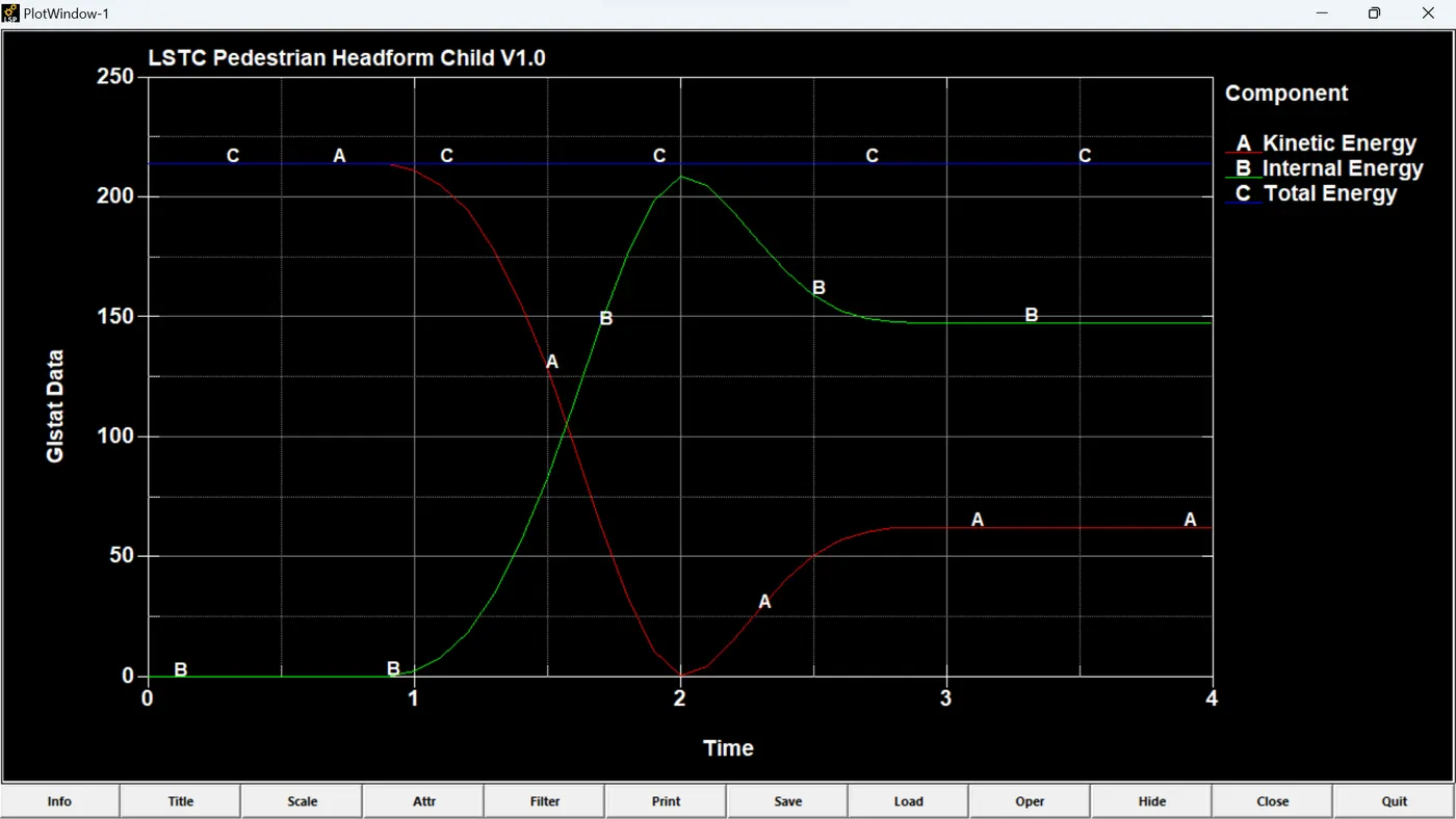
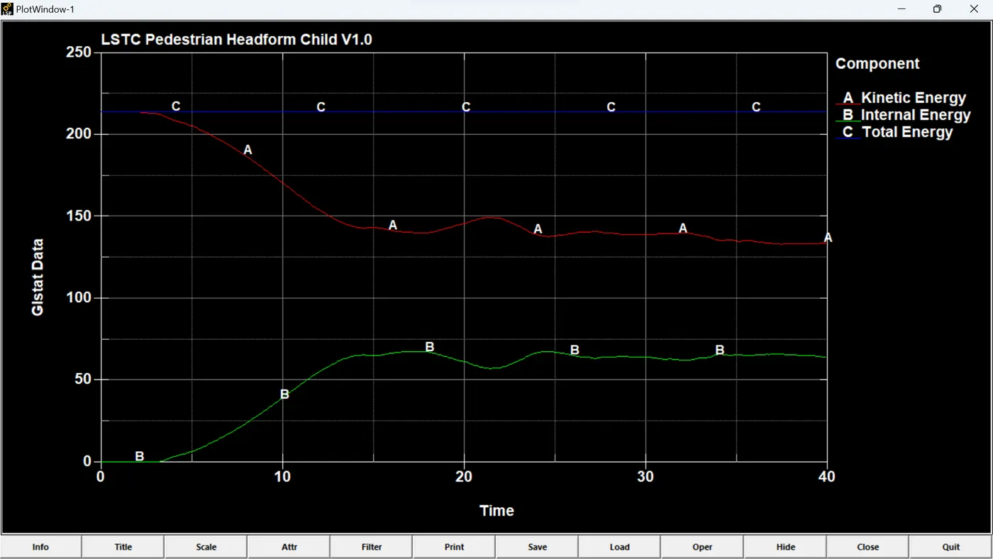
As one can observe from the energy plots that the there is a change in plots is due to change in the material properties in the head foam and hood.
VONMISES STRESS VARIATION:
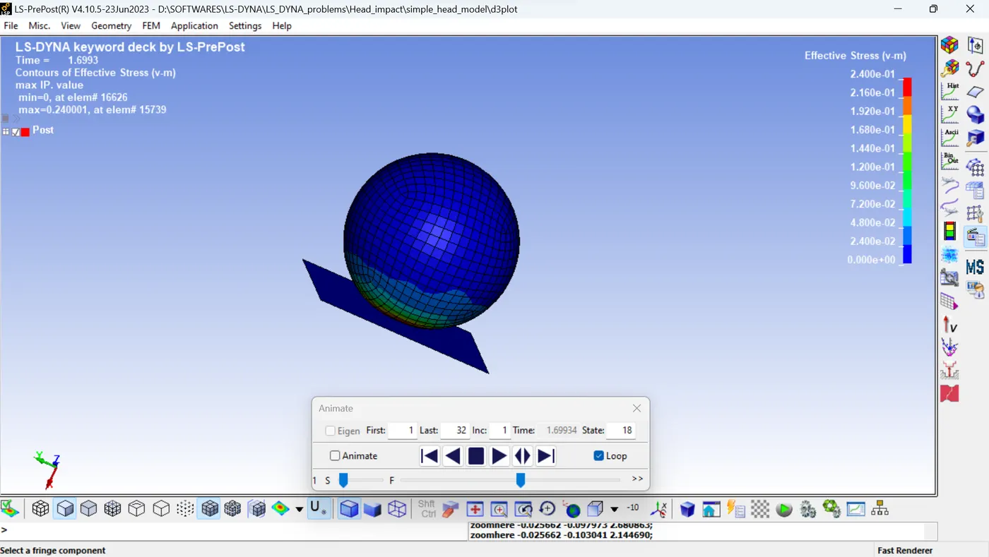
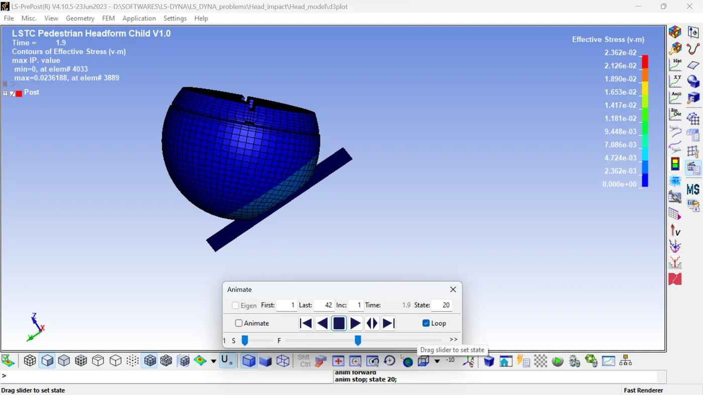
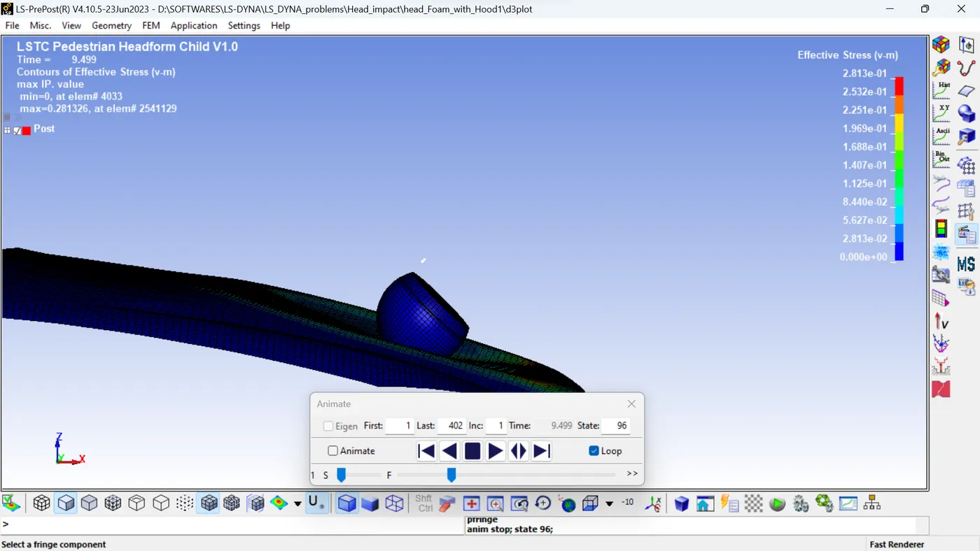
The maximum effective stress is attained at the time of impact and decreases. In Case 1 the maximum stress 240MPa and in Case 2 the maximum stress 23.6MPa and in the case 3 the maximum stress 283.1MPa.
HIC:
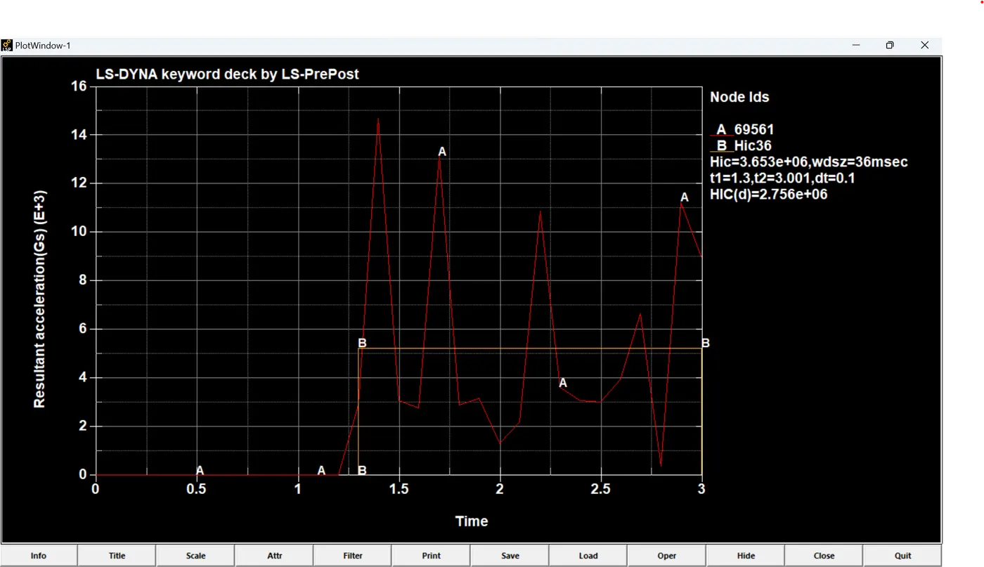
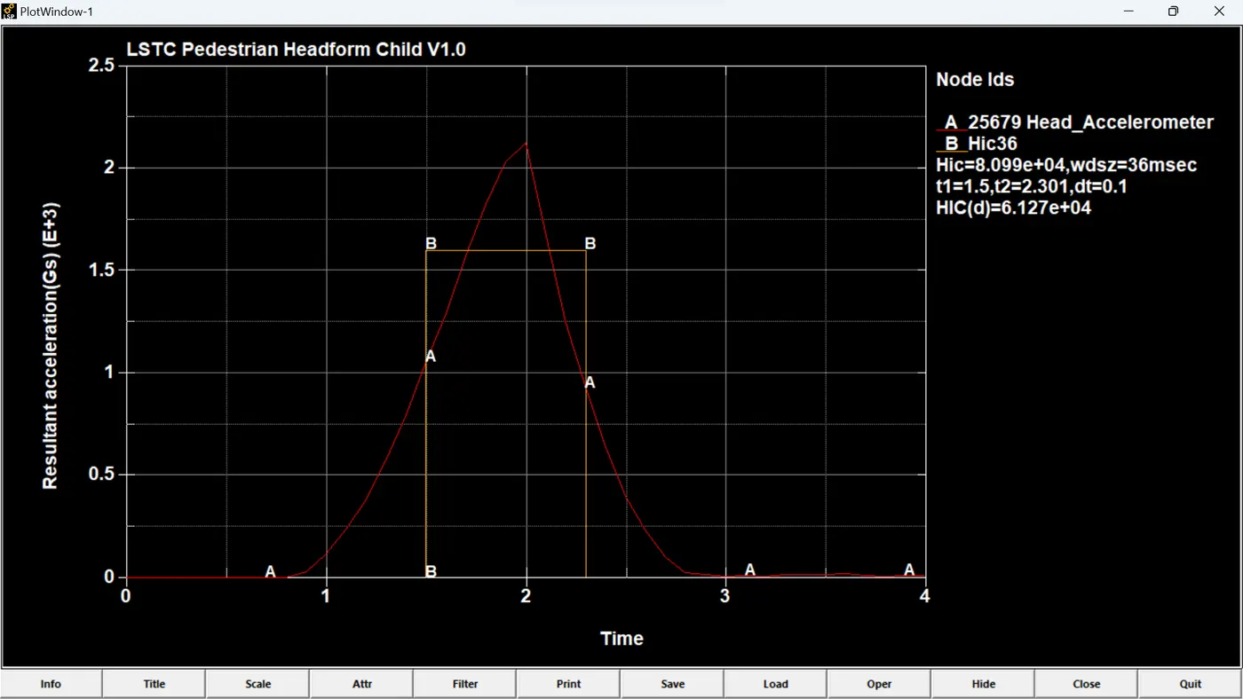
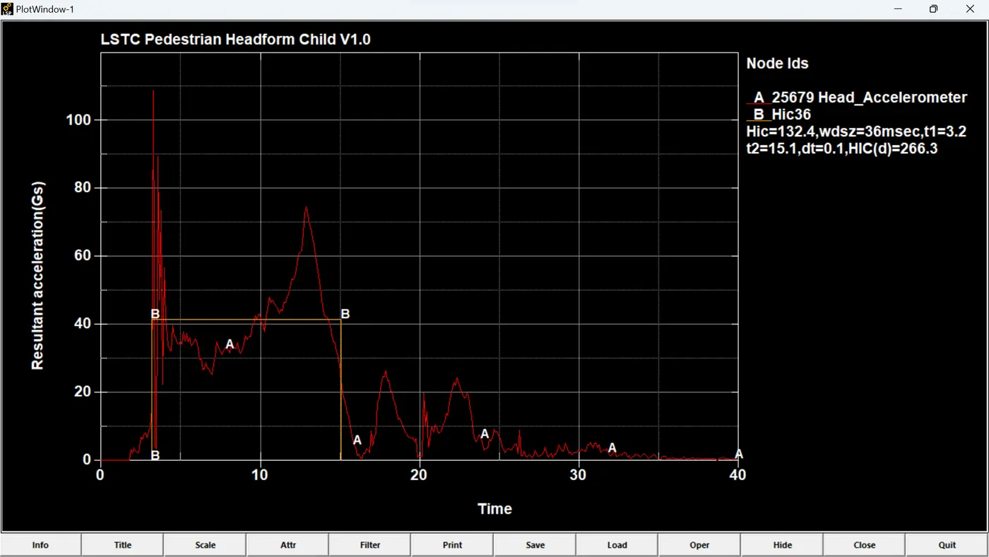
As we can see from the HIC plots the HIC36 value for Case 1 is 3.656e6, in Case 2 is 8.099e4 and in Case 3 is 132.4. The HIC value is decreasing as we go on introducing the material properties of actual case to the model.
CONCLUSION:
For the given model simulation of head impact is done and got the results accordingly.