Week-7 Head Impact
AIM
Pedestrian Head Impact
OBJECTIVE
- Creating RIGIDWALL Keyword.
- Head Impact test.
- Calculating HIC.
THEORY
Pedestrian protect CAE is a part of vehicle safety engineering from crash perspective in pedestrian protection, we look for imparting minimum injury to head, upper leg, lower leg in case of an accident with human subject.
HIC: It is a acronym of Head Injury Criterion. It is a measure of the likelihood of head injury arising from impact The HIC can be used to assess safety related to vehicle, personal protective gear, and sport equipment.
The formula for HIC is

Where t1&t2 are the initial and final times in seconds.
PROCEDURE
CASE:1 Simple head is impact with Rigidwall
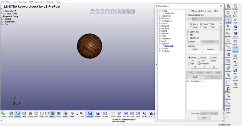
- Creation of Rigidwall: A RIGIDWALL is created for impact with head.
MODEL < CREENT < RIGIDWALL < CREATE
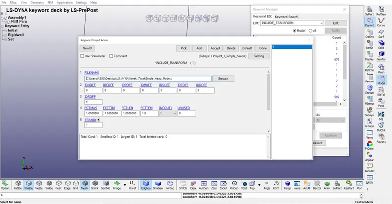
- Include: This keyword provides collecting different ls dyna files in one file.
MODEL < KEYWORD < INCLUDE < TRANSFORMATION
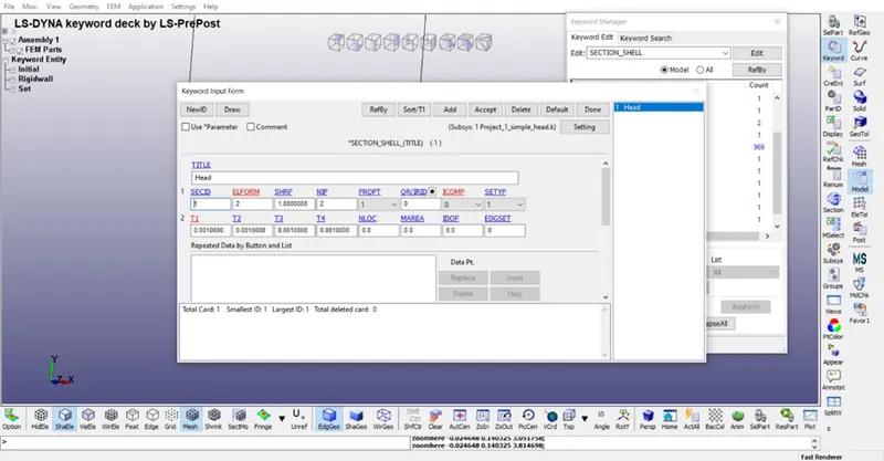
- Section: In this HEAD is defined as SHELL section.
MODEL < KEYWORD < SECTION < SHELL
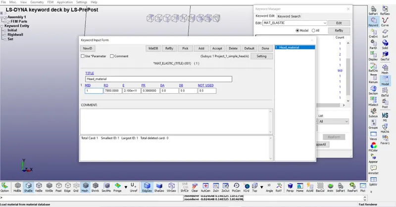
- Material: In this material of head is defined. For head elastic material is considered.
MODEL < KEYWORD < MAT < 001-ELASTIC
- Part: In this both section and material is connect .
MODEL < KEYWORD < PART
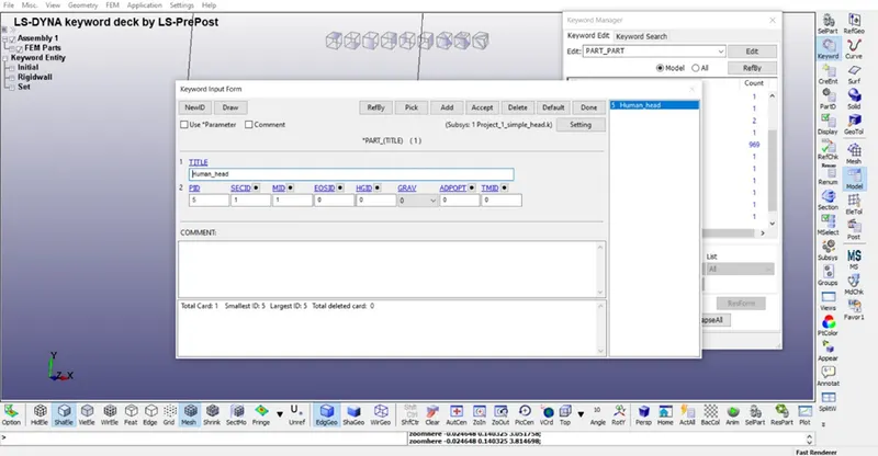
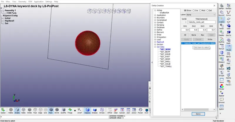
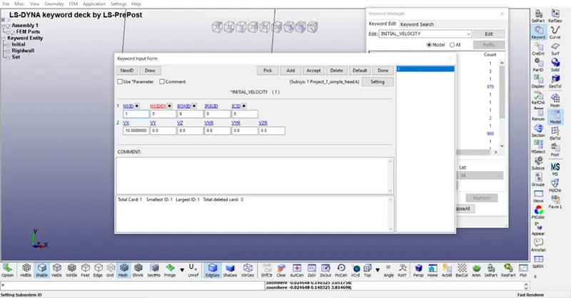
- Motion: For movement of the head initial velocity card is defined.While defining velocity node set is first defined with all node of human head mesh.
MODEL < CREENT < SET_NODE
MODEL < KEYWORD < INITIAL < VELOCITY
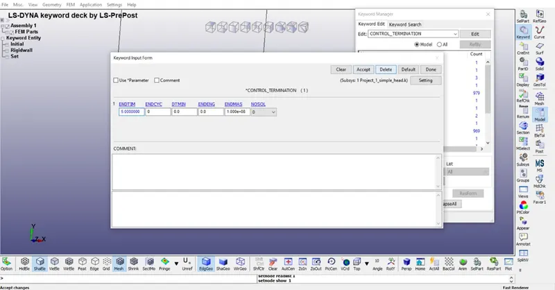
- Termination: In this time is set for termination the simulation.
MODEL < KEYWORD < CONTROL < TERMINATION
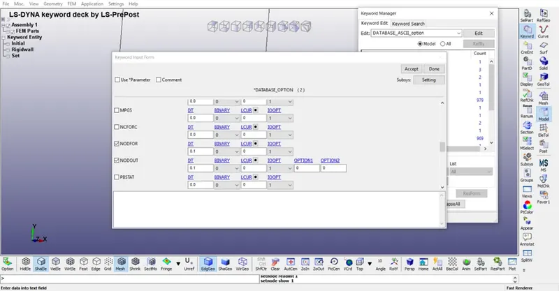
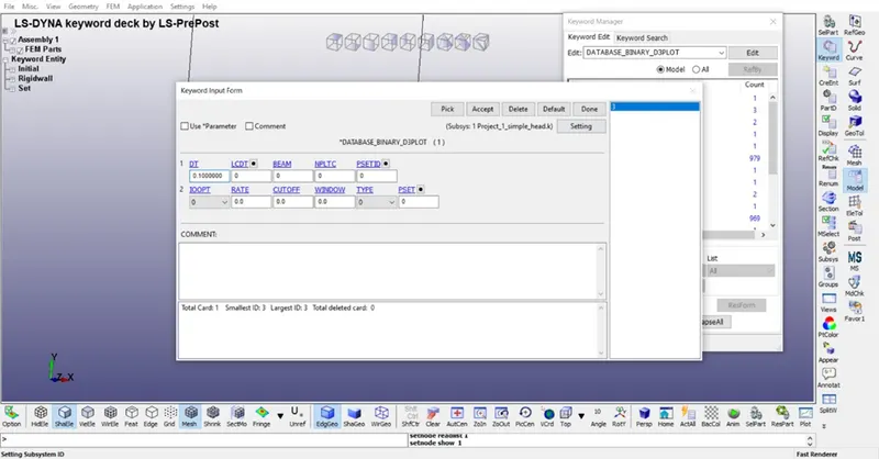
- Output file: In this different output file is provided.
MODEL < KEYWORD < DATABASE < ASCII
MODEL < KEYWORD < DATABASE < BINARY D3PLOT
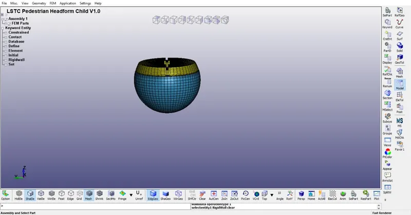
CASE:2 Headform is impact with Rigidwall
In this simulation all the process and procedures are same however in place of simple head complicated modellled head is used.
CASE:3 Headform is impact with Hood.
- Include: This keyword provides collecting different ls dyna files in one file.
First head model is included in this file through *INCLUDE. For including first, we have to transform a include file for which transform keyword is defined from define.
MODEL < KEYWORD < DEFINE < TRANSFORMATION
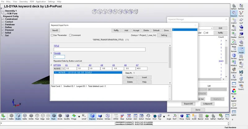
MODEL < KEYWORD < INCLUDE < TRANSFORMATION
- Section: In this Hood is defined as SHELL section.
MODEL < KEYWORD < SECTION < SHELL
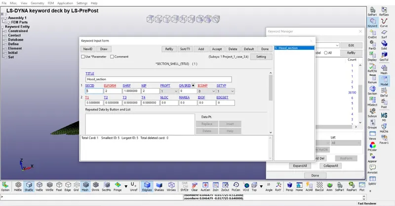
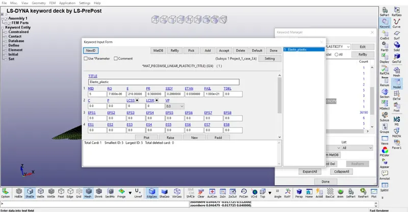
- Material: In this material of hood is defined. For head Peacewise Linear plasticity material is considered.
MODEL < KEYWORD < MAT < 024- PEACEWISE LINEAR PLASTICITY MATERIAL
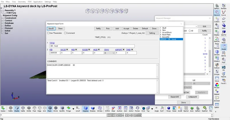
- Part: In this both section and material is connect .
MODEL < KEYWORD < PART
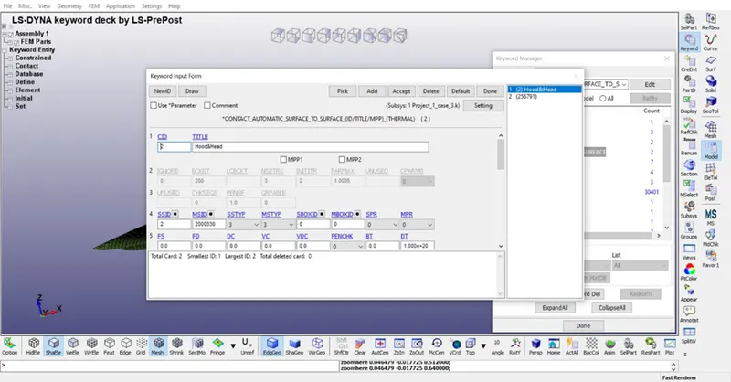
- Contact: In this section contact between hood and head skin is defined.
MODEL < KEYWORD < CONTACT < AUTOMATIC SURFACE TO SURFACE
- Motion: For movement of the head initial velocity card is defined. While defining velocity node set is first defined with all node of human head mesh.
MODEL < CREENT < SET_NODE
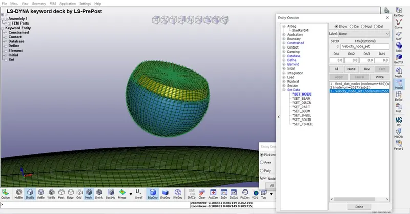
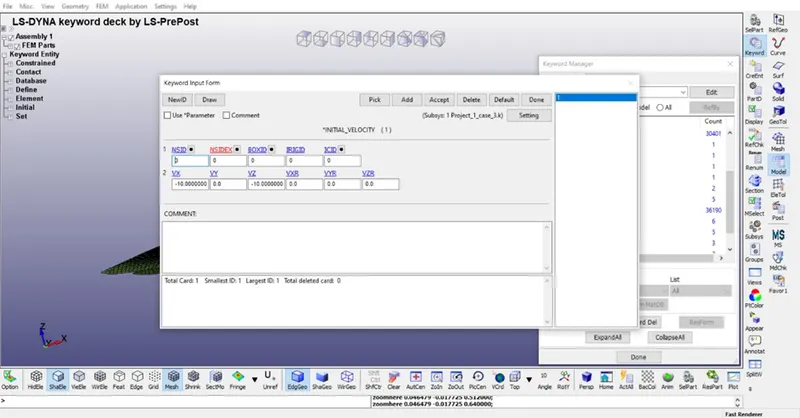
MODEL < KEYWORD < INITIAL < VELOCITY
In this for velocity calculation is
Vx = Cos 45 *initial velocity (Cos 45 is because at Define < transformation we given 45 degree).
Similarly
Vy = Sin45 * initial velocity.
- Termination: In this time is set for termination the simulation.
MODEL < KEYWORD < CONTROL < TERMINATION
- Output file: In this different output file is provided.
MODEL < KEYWORD < DATABASE < ASCII
MODEL < KEYWORD < DATABASE < BINARY D3PLOT
Simulation
Case 1
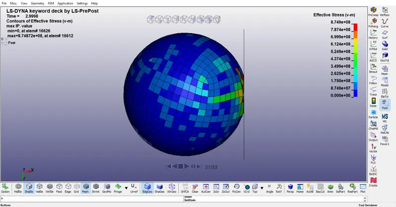
Case 2
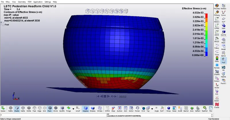
Case 3
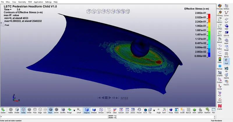
RESULTS
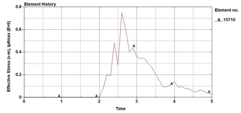
Case 1
Stress plot
HIC plot
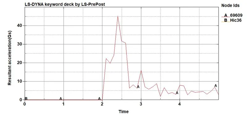
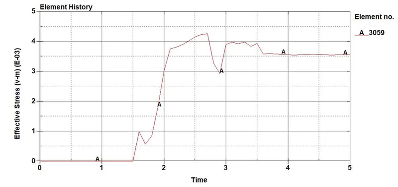
Case 2
Stress Plot
HIC plot
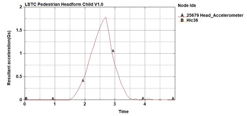
Case 3
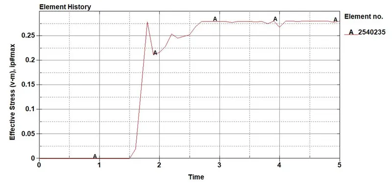
Stress Plot
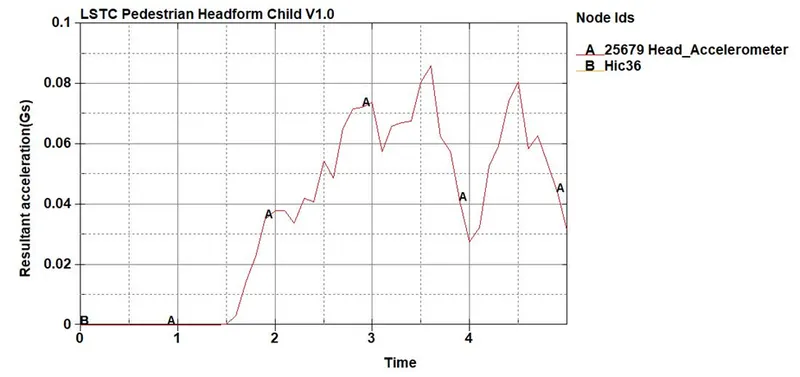
HIC plot
CONCLUSION
From simulation and graph it is found that maximum stress is at strike point and different hic is found.