Week-7 Head Impact
Week-7 Head Impact
Aim: Simulate the given model with different bodies by assigning the appropriate key cards.
Explanation:
The given model has to be run in three steps
- First the simple head impact model is simulated with crash on Rigid wall
- Next the simple sphere is replaced by given head foam model and is simulated to crash on rigid wall
- Last the rigid wall is replaced by given meshed hood model
- First the simple head impact model is simulated with crash on Rigid wall
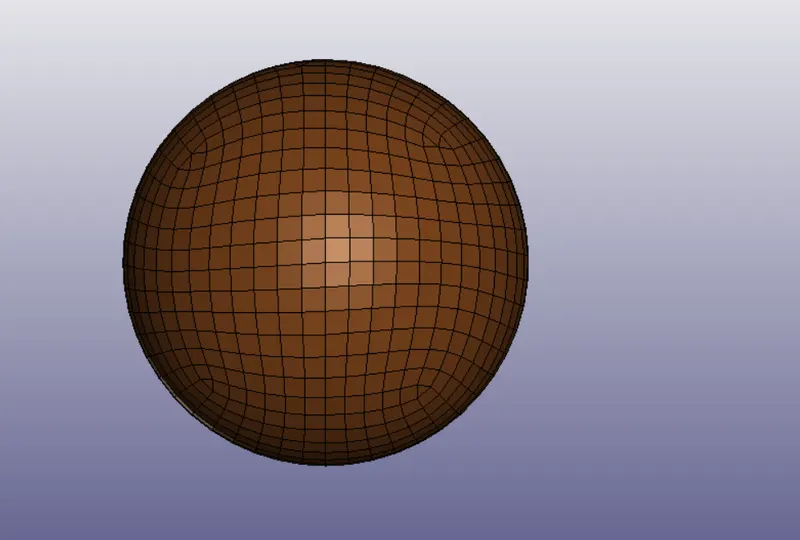
Here the Simple_Head_Model.k is opened in LS PrePost from File -> open
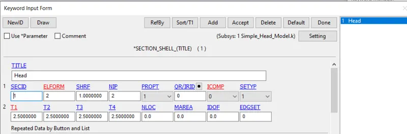
1) Defining Section card for shell from key word manager -> all -> section -> shell
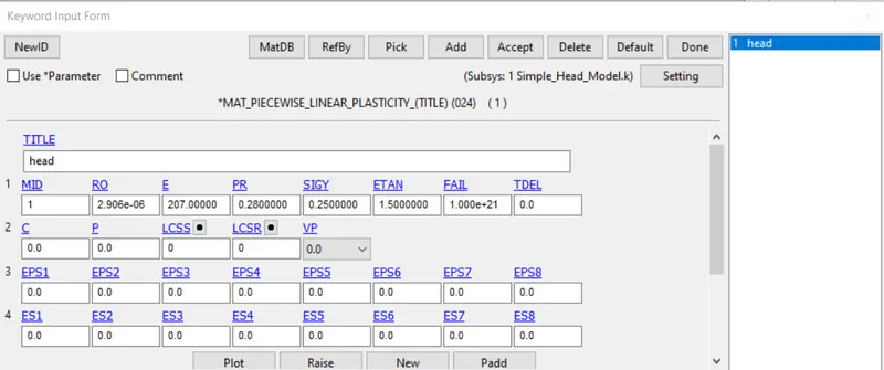
3) Material card generation from key word manager -> all -> MAT -> Type 24 for linear plastic material.
The values are with repect to the given unit system.
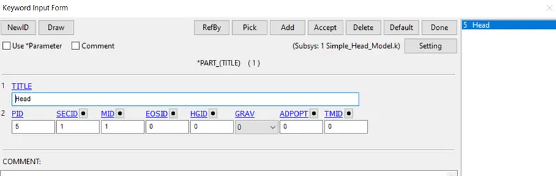
After the section id and materail id are created, they are then assigned to the parts in the model.
From key word manager -> model -> PART in SECID and MID for Box
4) Rigidwall
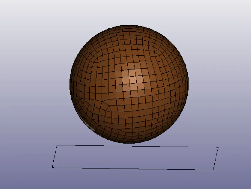
This crash is to happen with the rigidwall and this is formed
From Model and Part -> Entity Creation -> Rigidwall
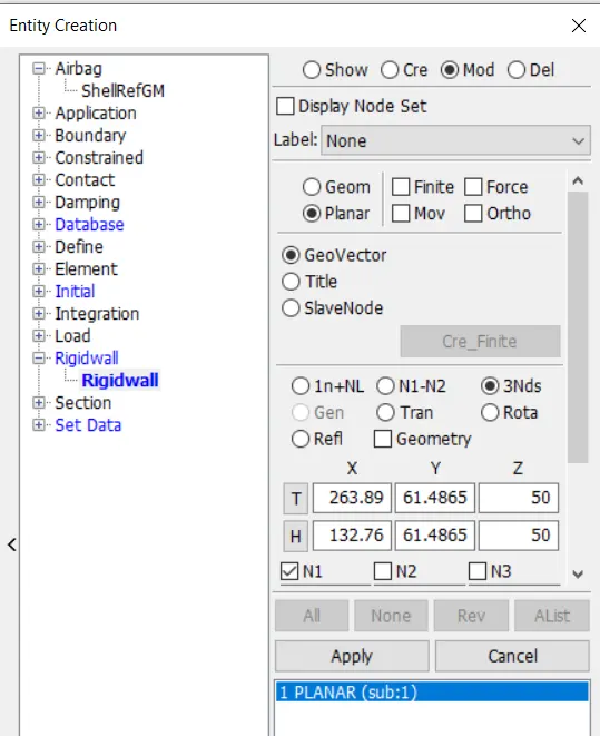
Here the N1, N2 and N3 are taken at extreme end of the sphere in a way such that the normal is towards the body and this rigidwall is translated away using tran option from above, so that crash can happen after a time.
5) Intial Velocity
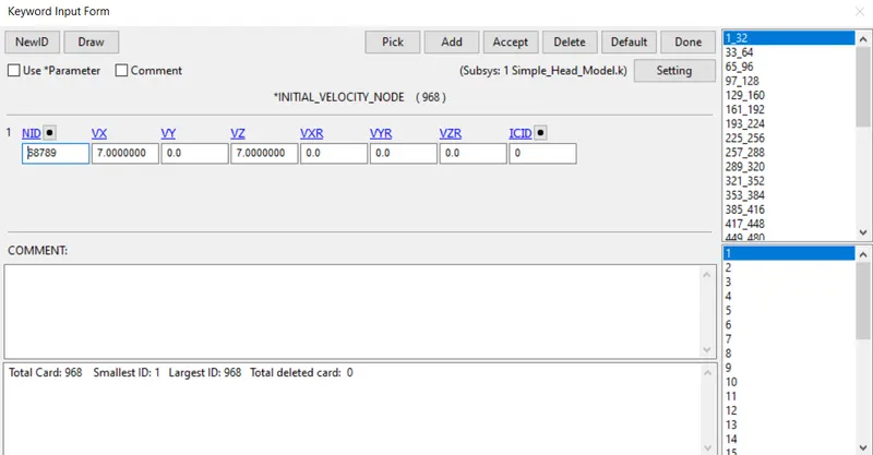
This velocity for the box is taken to be in +ve xz direction and all the nodes of the part are picked
The velocity is gen such that the velocity vector make an angle of 45 degree with the rigid wall as recommeneded and the velocity resultant is taken about to be 35.6 KMPH as recommended range
From Model and Part -> Entity Creation -> Intial -> Velocity
This can be seen from keyword manager.
6) Contact card
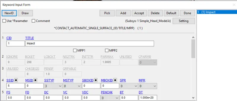
Since it is collision with rigid wall, we use AUTOMATIC_SINGLE _SURFACE, we can just define slave nodes
7) Control cards
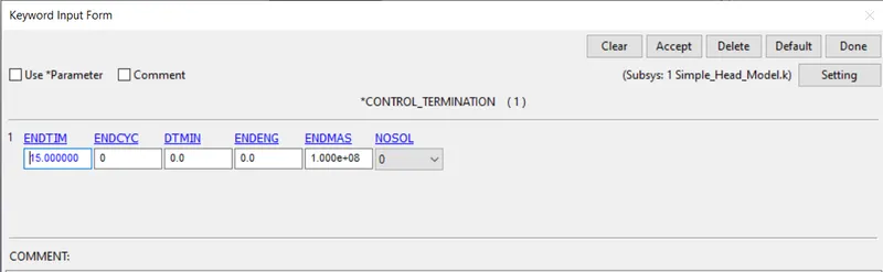
After the contact, control cards are chosen fron keyword manager -> all -> control -> Termination
The end time is chosen to be 15 ms to check before and after collision
7) Database card
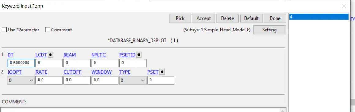
After the control cards, the output requests are updated from Keyword manager -> all -> Database ->
Binary_d3plot for contours and animations
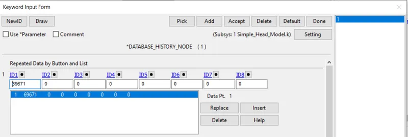
History node for getting acceleration at specified node at end
The energy values, forces on parts, nodes are updated in ASCII
GLSTAT for energy values
NODOUT for values at specified node
RCFORC for contact forces
with DT as 0.5 ms
2. Next the simple sphere is replaced by given head foam model and is simulated to crash on rigid wall
After simulating the sphere with rigid wall model, we open a new LS PrePost and save it as Impact.Dyna file
Here we use Include card to import an additional head foam model into this Impact.Dyna keyword file
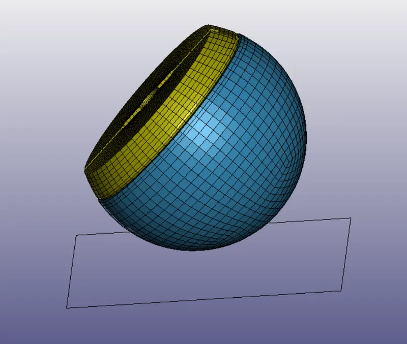
Before Importing we define Transformation card from Define keyword so that the head is properly aligned at an angle of 45 Degree with the Rigid wall which is horizontal to x axis.
This is done by rotating the head model about y axis aroung 45 deg
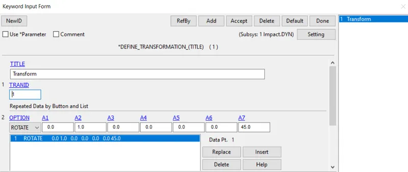
After this is done we go for Include Tranform card to import the Head foam model, by browsing the location and the file.
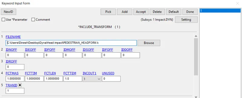
When we are doing any card operations, we make sure they are in Impact .DYN subsystem
Similar to first step rigid wall and intial velocity is set for the Headfoam model in Impact.DYN subsystem.
The control and Database cards are given as same as first step in addition to the cards present and the model is saved.
3. Last the rigid wall is replaced by given meshed hood model
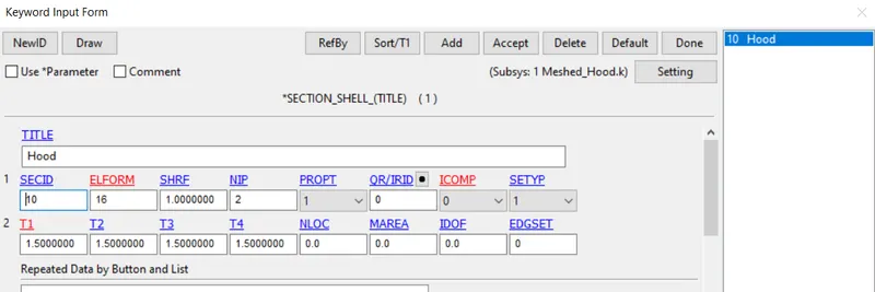
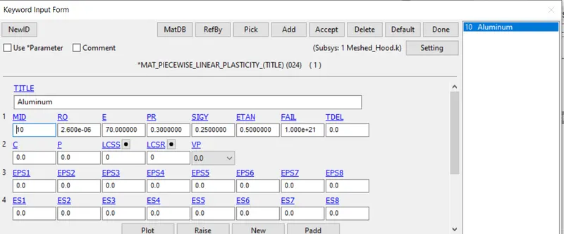
The hood model is checked in Notepad and we can see the section and material is not defined , so this Hood.k file is opened in LS PrePost and here the section ID and Material ID are defined.
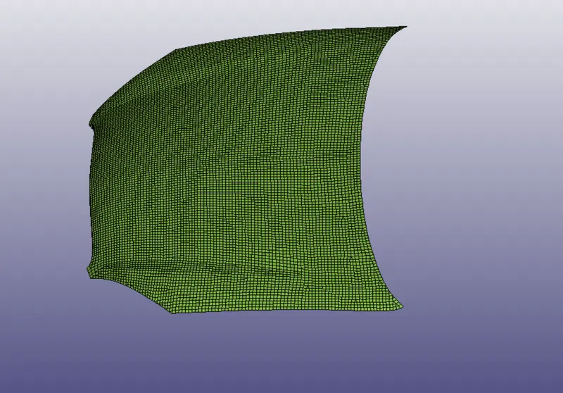
This Hood.k file is then saved.
Finally the Second model is taken and the rigid wall is removed along with the contact card, for crash into rigid wall
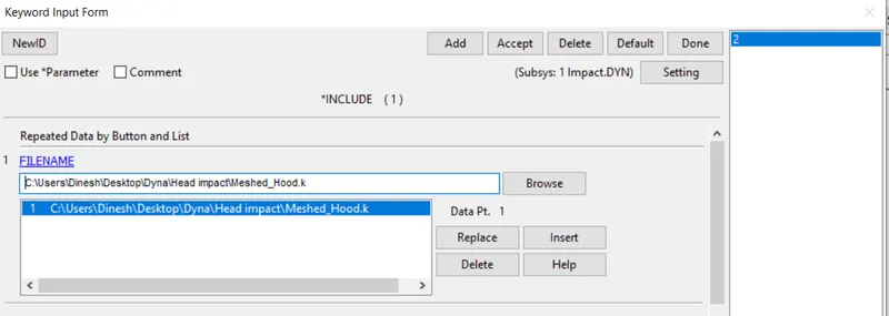
Then using Include card The Hood model is imported into the Impact.DYN file
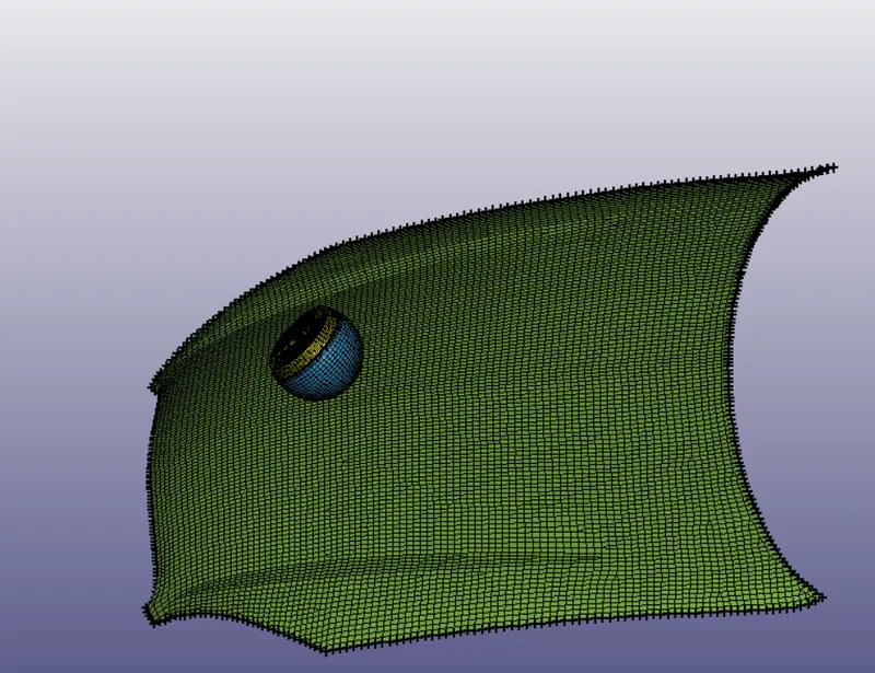
After Hood model is imported the boundary nodes of the hood are constrained so that the hood doesn't move from create entity -> Boundary conditions -> Spc
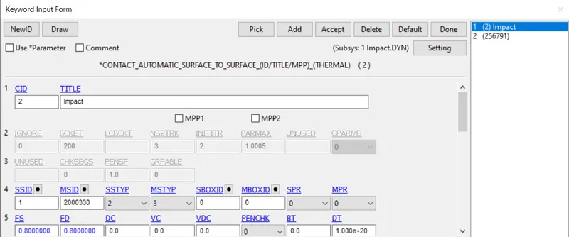
In addtion to this the contact card is defined for contact between the two meshed bodies where the slaved parts are taken to be the headfoam parts and the master part is taken to be hood model.
8) After this keyword cards are created and updated, then this keyword file is saved.
Then opening LS RUN and choosing the modified keyword file and run all the models
Results:
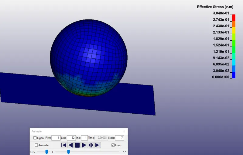
The d3plot is opened as binary file in LS prepost and following max stress contour is obtained around time of impact for model 1.
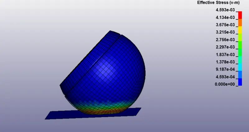
The d3plot is opened as binary file in LS prepost and following max stress contour is obtained around time of impact for model 2
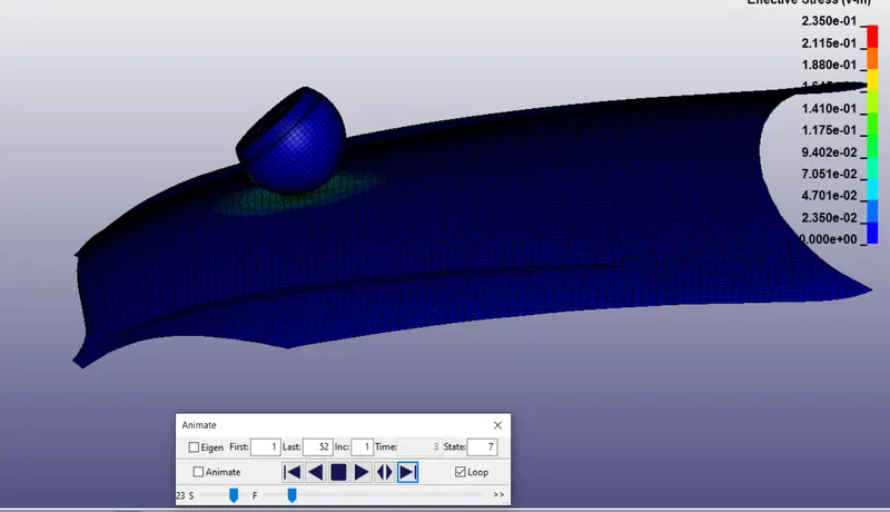
The d3plot is opened as binary file in LS prepost and following max stress contour is obtained around time of impact for model 3
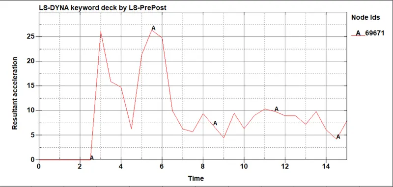
Acceleration plot at specified node for model 1 from nodout on Ascii
Acceleration plot at specified node for model 2 from nodout on Ascii
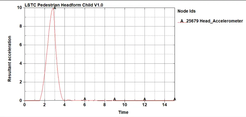
Acceleration plot at specified node for model 3 from nodout on Ascii
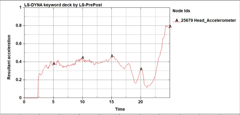
The HIC values for head impact are taken from Plottin acceleration and hic 36 on same plot
HIC for Model 1 (Sphere impact on rigid wall)
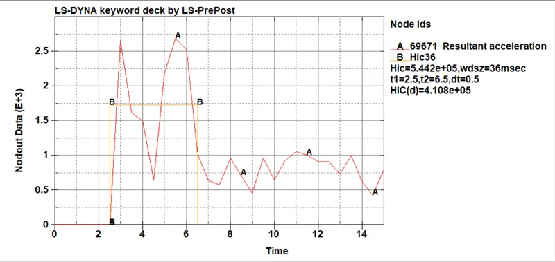
The value of HIC 36 shown is in order of 10^5 since this crash is of rigid wall and spherical head with approximate properties the value is high.
HIC for Model 2 (Head foam model impact on rigid wall)
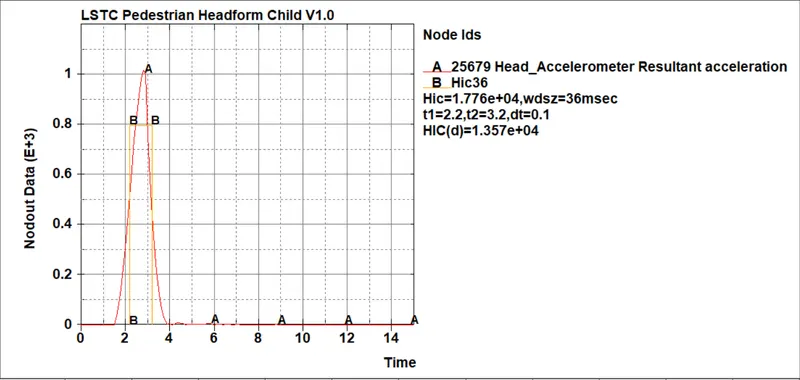
The HIC value is still high as we have taken crash with rigid surface and this HIC is taken for 2 ms
HIC for Model 3 (Head foam model impact on Hood model)
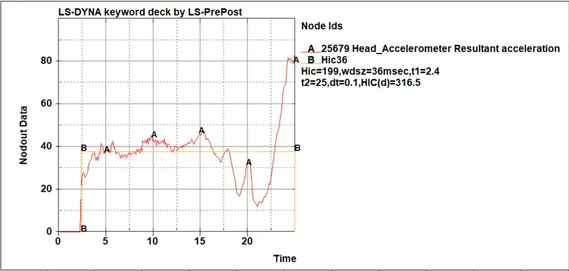
The HIC(d) value we got is 316.5 which is within norm because we have taken the head model and hood with aluminum material.
Conclusion:
Learned calculation of HIC
Learned the usage of Include keyword.
Learned to transform and import additional keyword file into a single keyword file.
The given models for all three cases are successfully simulated in LS Dyna.