Week 7 - Creating connection for Rear door
Week 7 - Creating connection for Rear door
AIM: Establishing connections between regions through the application of RBE2 and RBE3 elements.
PROCEDURE:
Step 1 – Import the provided rear door model into the ANSA software.
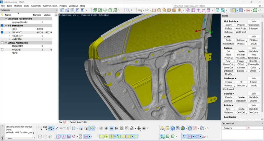
Figure – 1 DOOR MODEL
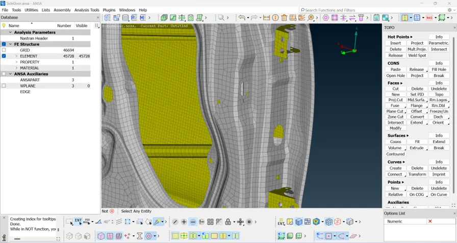 Figure – 2 DOOR MODEL HINGE REGION
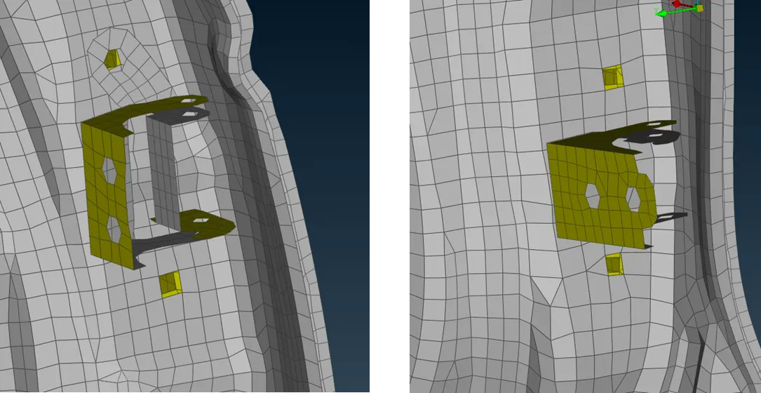
Figure – 3 BOLT REGION OF THE HINGE
Step 2 – Assign PID (Product Identification) codes to the model to facilitate seamless connection and integration of bolt regions.
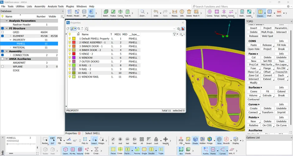
Figure – 4 PIDs ASSIGNED.
Step 3 - Once the bolt regions are identified, generate 3D points along the perimeter of the bolt holes. Subsequently, convert these bolt holes into bolt elements using the Convert Manager. In the Connection Manager, specify the element type as bolt holes and define P1, P2, P3. Choose the in-X out-X scenario. Lastly, generate the bolt as an RBE-2 element, ensuring the user defines the appropriate search distance, element type, and constraints on degrees of freedom to properly constrain the body.
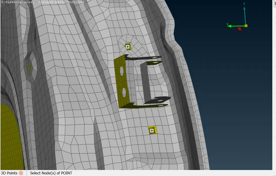
Figure – 5 3D POINT SELECTED TO DEFINE BOLT AND BOLT ELEMENT
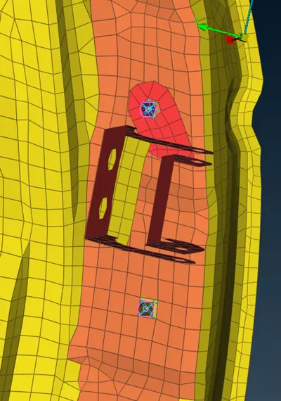
Figure – 6 RBE 2 ELEMENTS DEFINED ON THE BOLT REGION.
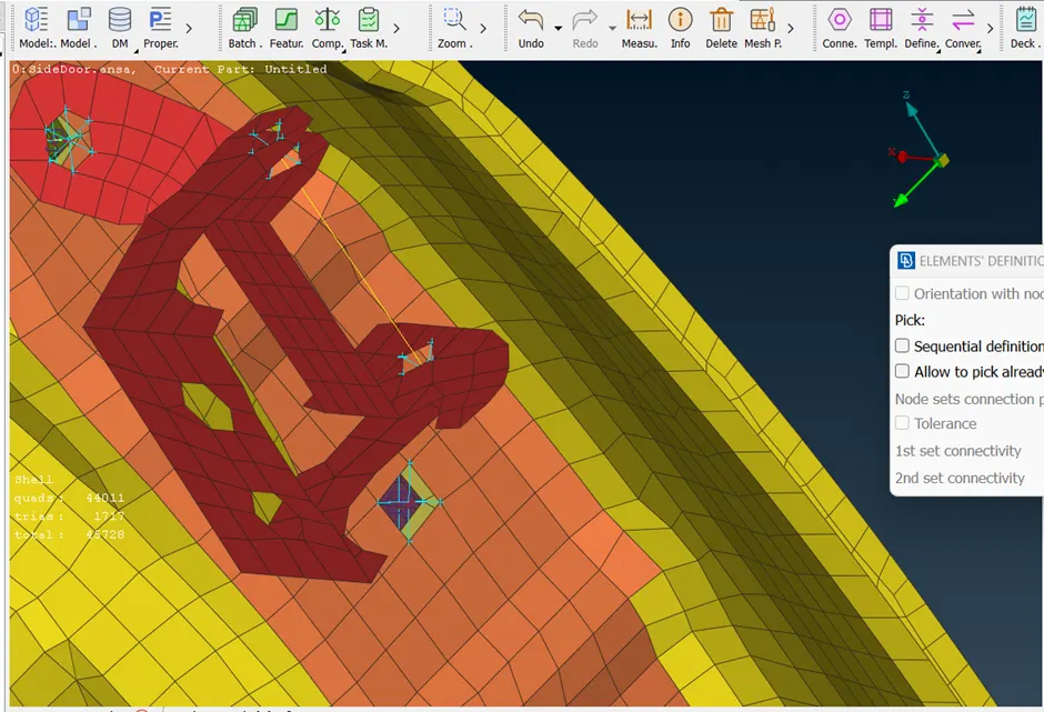
Figure – 7 COMPLETE HINGE PORTION HAS BEEN RIGIDISED.
Step 4 – For the hinge portion the element has to be constrained in all directions except for rotation in the Z-direction, meaning only translational degrees of freedom (CM in 1, 2, 3, 4, 5) should be enabled.
Figure – 8 REGIONS WHERE RBE 2 ELEMENTS ARE DEFINED.
Step – 5 Once all the RBE 2 elements have been defined, the next step involves the connection of the door handle.
Define RBE 2 Elements:
Place RBE 2 elements in both holes of the door handle. The RBE 2 (Rigid Body Element Type 2) is typically used to connect multiple nodes together, providing a rigid connection. Ensure that the RBE 2 elements are appropriately located and oriented to establish a connection between the handle and the surrounding structure.
Define Constraint Mass:
Create a constraint mass at the center of the RBE 2 elements. The constraint mass represents the concentrated mass at the connection point, simplifying the modeling of the handle's mass for analysis purposes.
Check Constraints and Connectivity:
Verify that the RBE 2 elements and the constraint mass are correctly defined in the model. Ensure that the connectivity between the handle and the surrounding structure is accurately represented.
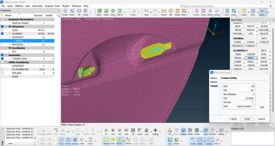
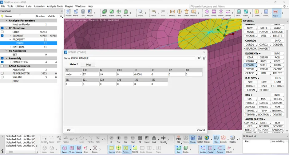
Figure – 9 DOOR HANDLE RIDIGISED AND CON MASS DEFINED.
Step – 6 To secure the door rail mechanism in place, it is necessary to affix it using a series of spot welds and employ cluster RBE2 elements to reinforce and rigidify the mechanism.
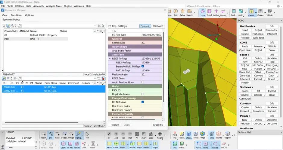
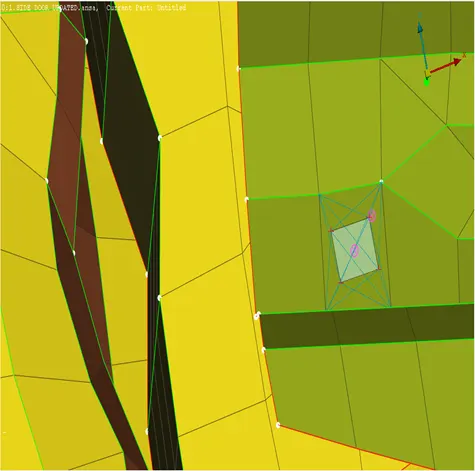
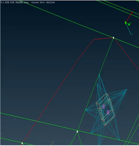
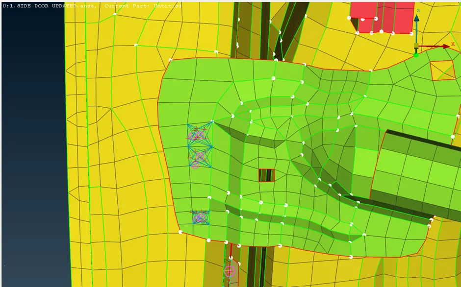
Figure – 10 SPOT WELD AND CLUSTER RBE-2 DEFINED ON THE RAIL MECHANISM
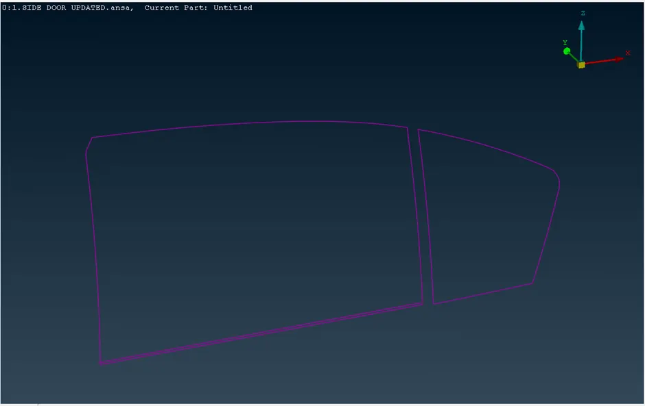
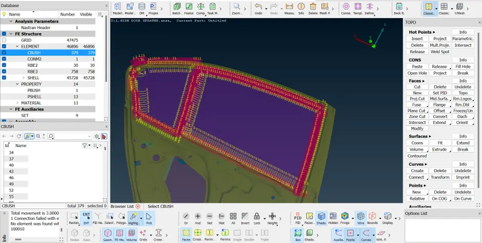
Step – 7 To enhance the structural integrity of the rear door windows, RBE3-CBUSH-RBE3 elements were employed as they accurately represent the weather strip surrounding the window. The process involved creating curves along the window frame edges, converting these curves into spot line representations via the conversion manager, and subsequently transforming these spot lines into CBUSH RBE3 elements using the connection manager. Prior to generating the CBUSH elements, it is advisable to define the spacing distance and ensure the "keep all branches" option is selected for optimal results.
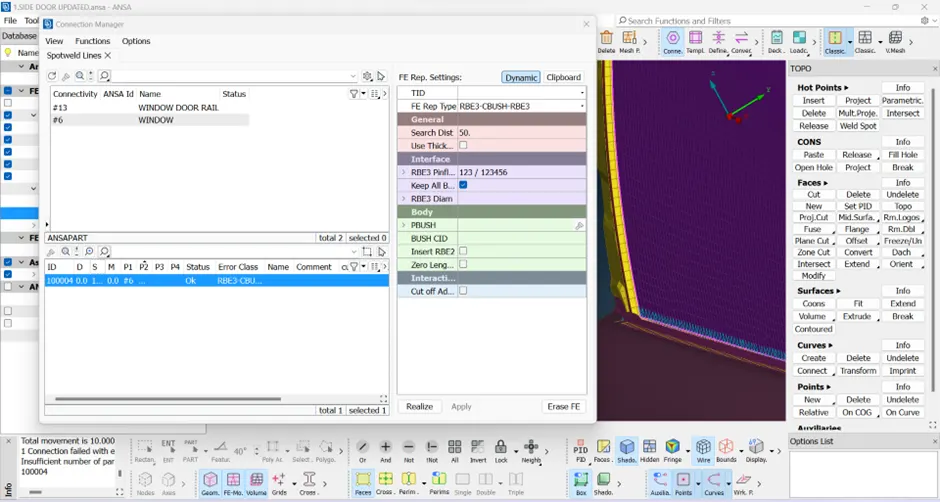
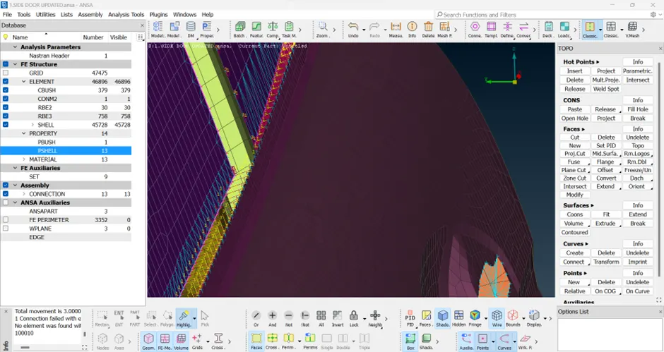
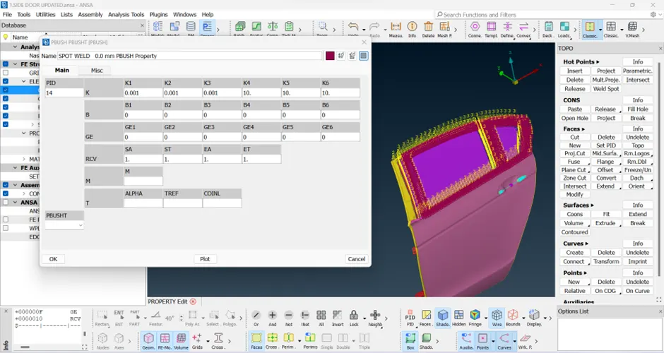
Step – 8 In the concluding step, it is essential to define the stiffness matrix for the CBUSH elements. This matrix specifies the structural stiffness properties that govern the behavior of the connection. Accurately defining the stiffness matrix ensures the proper simulation and analysis of the structural response for the CBUSH elements integrated into the rear door windows.
Conclusion.
Upon successful completion of the challenge, it is evident that a comprehensive understanding of the mechanism is crucial for any model. This understanding serves as the foundation for making informed decisions during the analysis, especially in terms of assigning connections. While the general procedure for establishing connections remains consistent across various models, the specific requirements for connection assignment may vary based on the unique demands of the analysis.
In the context of NVH (Noise, Vibration, and Harshness) analysis, it was imperative to effectively capture and address the influence of the weather seal. The utilization of CBUSH elements played a pivotal role in achieving this objective. The connection methodology employed not only rigidized the relevant areas but also established connections tailored to the specific analysis requirements. By doing so, the model successfully covered and addressed key aspects, ensuring a robust representation of the structural dynamics for NVH considerations.
Learning Outcomes
1. Understanding the Mechanism: Comprehensive understanding of the mechanism is essential for effective decision-making in analysis.
2. Connection Consistency: While the connection procedure is generally uniform, specific requirements may vary based on the model's analysis needs.
3. NVH Analysis Emphasis: In NVH analysis, capturing and addressing elements like the weather seal is critical.
4. Effective Use of CBUSH Elements: CBUSH elements prove effective in rigidizing and connecting areas, catering to specific analysis requirements.
5. Tailored Model Representation: Tailoring connections based on analysis needs ensures a robust representation of structural dynamics.
6. Iterative Learning: Iterative processes, such as defining stiffness matrices, contribute to continuous improvement in modeling practices.
https://drive.google.com/drive/folders/1HHea807Knf3ymmvC8ASEj8gZIiC_MvY9?usp=sharing