Week-7 : Converting a detailed engine model to a FRM model
Introduction To FRM:
- Fast Running Engine Models are dynamic, fully-physical engine models that are designed specifically to run fast. While high-fidelity engine models are common place in the engine performance department, they are often too slow running to incorporate into system level models where long transient events may be simulated, or where the simulation model must respond faster than real-time, such as for HiL (Hardwarein-the-Loop) simulations. When simulation speed is of priority, high-fidelity GT-POWER engine models can be simplified into FRMs using a standard conversion process. It is up to the user how far to simplify the model, depending on the accuracy-vs.-runtime requirement.
- FRMs are able to achieve such fast run times by two means: (1) increasing the simulation time step size, and (2) decreasing the number of calculations per time step. These two means are often accomplished at the same time by lumping various flow volumes together which will reduce the total number of sub volumes and also allow for a larger time step size by increasing the effective sub volume length (which is responsible for the time step size). In addition to simplifying and combining flow volumes, there are additional solver options that can reduce the number of calculations per time step and, thus, further decrease the run time without changing the time step size.
Explore Tutorial 9
- The tutorial is covers the process of the detailed Engine model into Fast Running Models
Detailed GT-Power Model:
- This model is a 4-cylinder 2.0 liter turbocharged Gasoline Direct Injection (GDI) engine. The turbine wastegate is being dynamically controlled in order to target BMEP. A full-load speed sweep is being simulated, from 5000 RPM down to 1000 RPM. A semi-predictive charge air cooler is included such that the outlet temperature is predicted as a function of inlet gas temperature and mass flow rate, coolant temperature, and charge air cooler effectiveness.
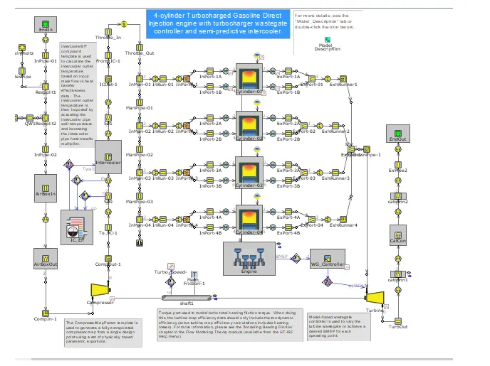
FRM can be done for the engine as follows
- Exhaust Manifold
- Exhaust Pipes
- Intake Manifold
- Compressor Pipes
- Intake Pipes
- Cylinder Slaving
Conservation Process:
Step-1:
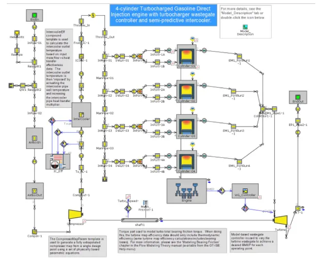
- In the first step we convert the exhaust manifold because the most of the times the exhaust manifold releases the Higher gases with higher velocities.
- Thus the below picture shows how we modified the Exhaust Manifold.
Step-2:
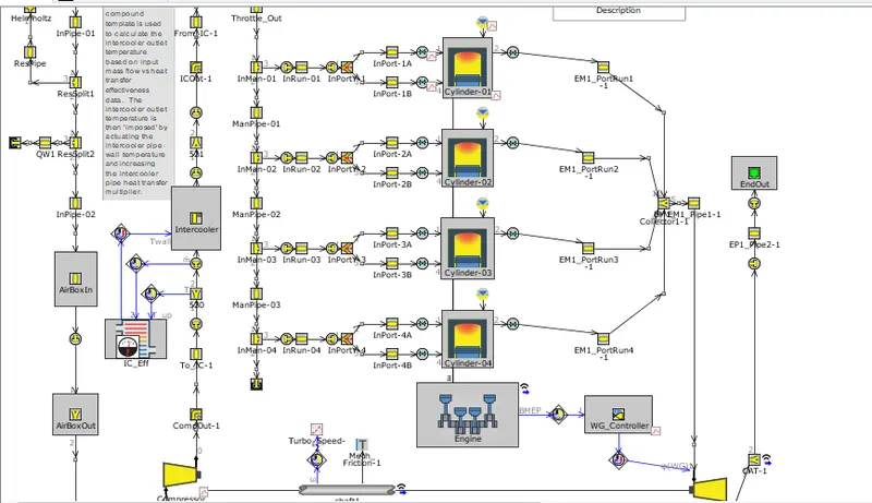
- The next step after the exhaust pipes downstream of the turbine where the gases flow into the outlet as shown in below.
- Thus the below Picture shows how the multiple pipes are modified.
Step-3:
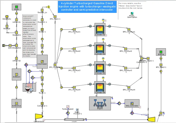
- In the next step we convert the intake manifold as per the Exhaust Manifold.
- Thus the below picture shows how we modified the Intake Manifold.
Step-4:
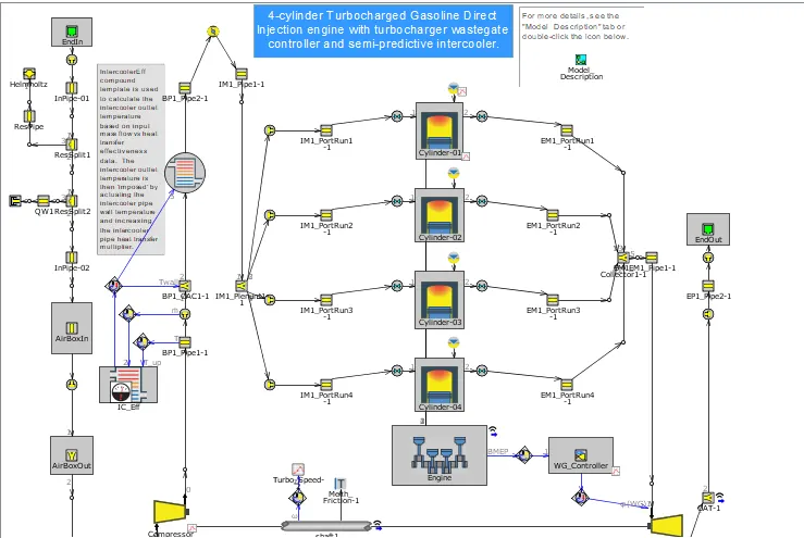
- Now we convert the Compressor Outlets pipes and intercoolers as shown in below.
Step-5:
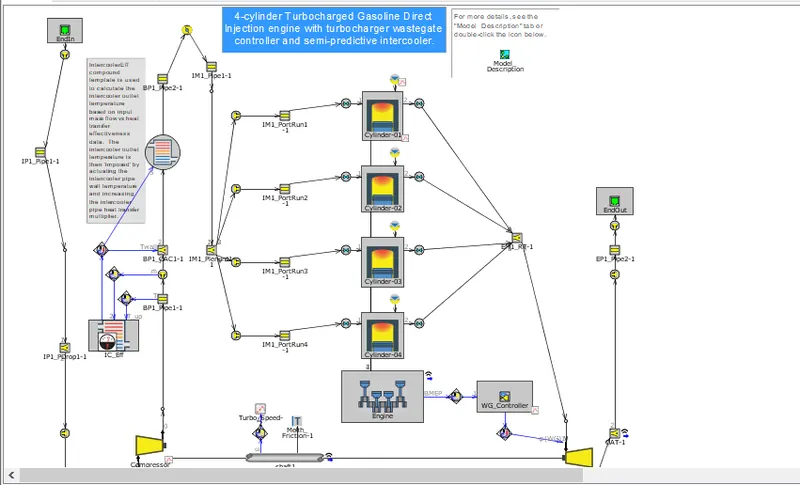
- Now the intake pipes should be modified where the air flows into the Compressor. Since every subsystem has now been simplified, we will assure that there are no remaining pipes with short discretization lengths
- Thus the below picture shows how we modified the intake pipes into the compressor.
Step-6:
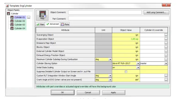
- The final simplification to the model will utilize the Cylinder Slaving capability of the EngCylinder component Name the new step "Cylinder Slaving", then collapse the FRM Converter to provide space to work in the model map.
- Right-click on any of the EngCylinder parts on the map and choose "Edit Parent Object". Go to the "Advanced" tab and for "Cylinder Slaving Option", select "slave-RT-full-v2018", then click OK. Now double-click on Cylinder-01, go to the "Advanced" tab, and set the Cylinder-01 override value of "Cylinder Slaving Option" to "master".
- For the full cylinder slaving to function, each Valve must be specified as either an Intake or Exhaust valve.The intake and exhaust valves are easy to distinguish. The intake ones start with "IM1_PortRun” and the exhaust ones start with "EM1_PostRun". Go to the Output folder and set "Valve Type for RLT Variable Calculations" to "intake", respectively "exhaust".
Step 7:
- Real-Time Solver (optional) Click "Next (Begin Next Step)" in the FRM Converter. Name this new step "Real-Time Solver", then collapse the FRM Converter. To run with the real-time solver, the license type of the model must be changed. However, certain templates are not allowed with the real-time solver, and so they must first be removed from the model.
- Thus the all modifications done in the model and started for the simulation.
Fast Running Engine Models (FRMs) from their detailed equivalent, so they can be used in a variety of integrated simulations. FRMs execute much more rapidly than the typical detailed GT-POWER engine model, and are ideal for integrating with other vehicle systems where an accurate and predictive engine plant model is desired and where computational speed is critical. FRMs adapt to changing conditions (e.g. valve timing, spark/injection timing, turbo lag, external temperature, altitude, cooling system conditions, etc.) without the need to apply non-physical correction factors. Whether studying changes to ambient conditions, or simulating events that are heavily transient in nature, FRMs will maintain the predictive capabilities of a detailed engine model while allowing for the fast computational speeds that are expected when performing drive cycle analysis and other transient-focused simulations.
Some examples of applications that are ideal for FRMs are:
- ECU Modeling (including HiL) – where a fast-running and transient-capable engine model is essential for optimizing ECU strategy
- Engine + Drivetrain/Vehicle – where accurate torque pulsations are key for optimizing drivetrain design and strategy
- Vehicle Thermal Management modeling, where the engine provides the heat to the cooling system, and the cooling system behavior feeds back into the engine performance predictions (great for simulating off-ambient conditions)
FRM MODEL BUILDER (Using FRM Builder Approach):
- Following steps are to be done for the building the FRM model using the below technique
Go to the tools select the FRM Builder Icon as shown in below:

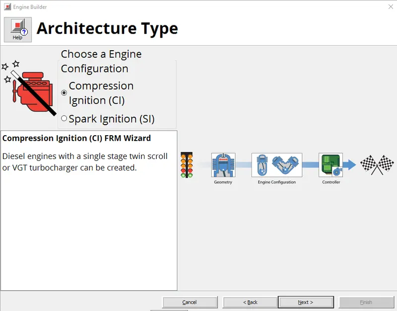
Select the CI Engine Model:
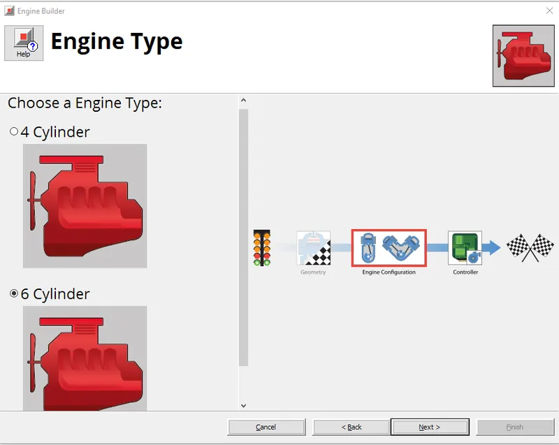
Select the 6 engine Cylinder Configuration:
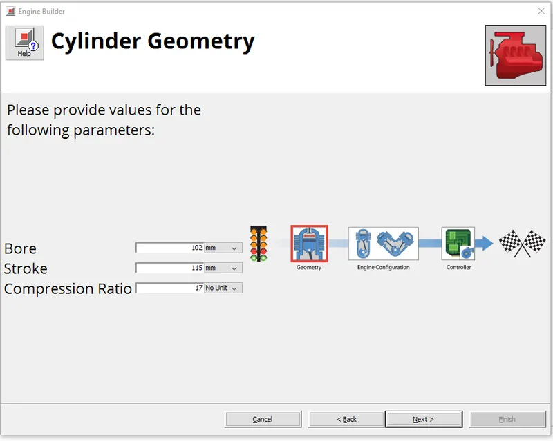
Enter the geometry details like Bore, Diameter and Compression Ratio as per given in the below:
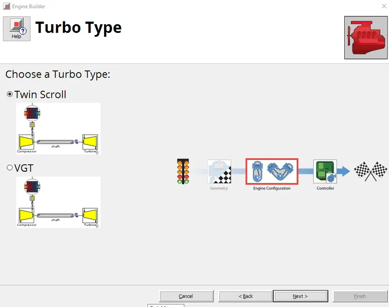
Select the twin Scroll Turbine:
Select the GT-Suite Controller as a logic Circuit as per shown below:
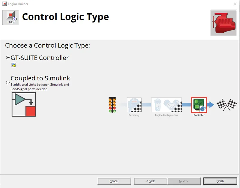
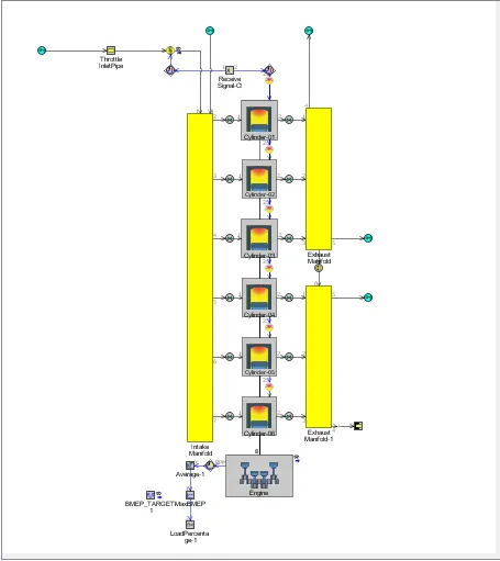
Select finish and the Desired FRM model is generated:
The Detail Engine is shown below:
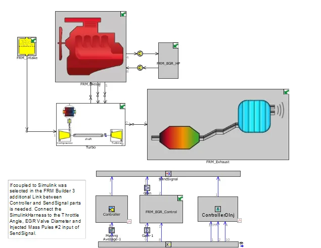
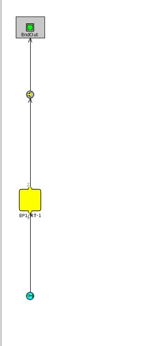
The FRM Exhaust:
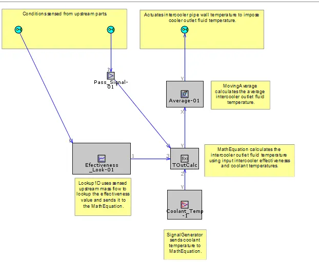
EGR Efficiency:
FRM_EGR-HP:
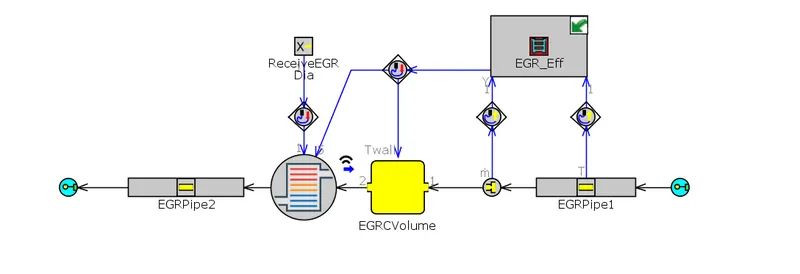
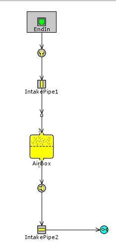
FRM_Intake:
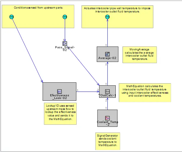
IC_Efficiency:
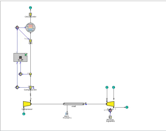
TurboCharger:
FRM_EGR_Control:
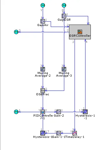
FRM_Diesel:
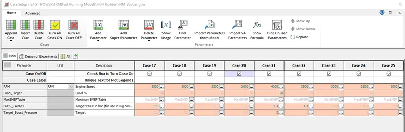
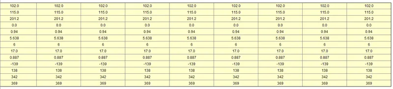
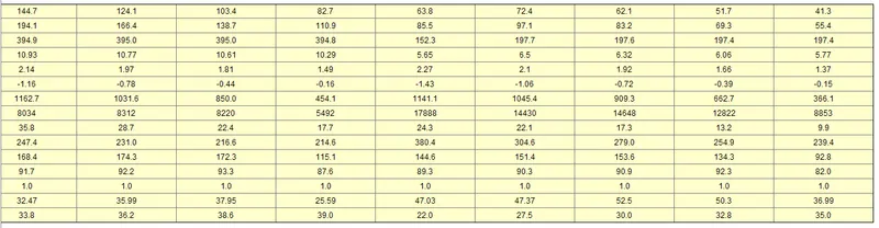
The following case is set up for 25 Case setups and shown below in 3 Case setups:
Cases are shown below in the 3 sub cases due to the unavailability of data to be viewed
Case SetUp I:
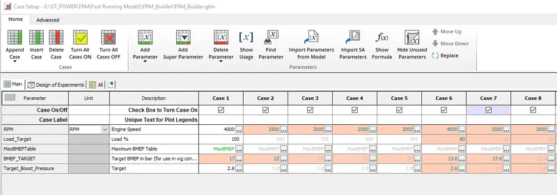
Engine_Geometry_Details:
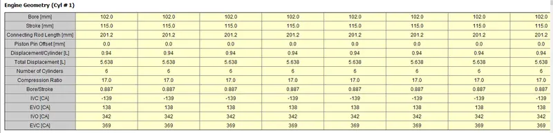
Engine-Performance_Details:
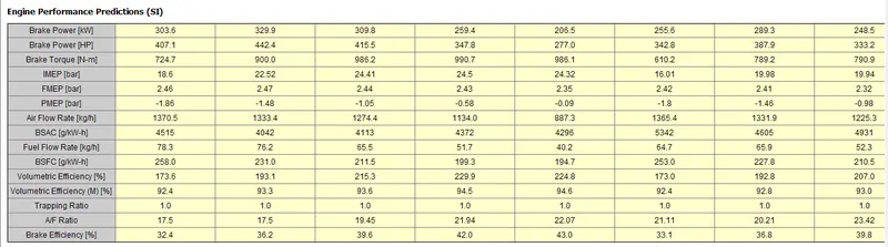
Case SetUp II:
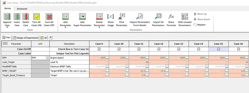
Engine_Geometry_Details:
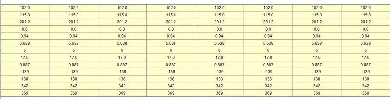
Engine-Performance_Details:
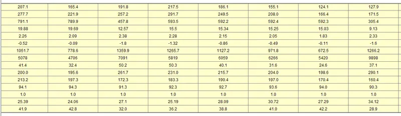
Case SetUp III:
Engine_Geometry_Details:
Engine-Performance_Details:
Now run the simulations and obtain the results as shown in below:
Results of Time Table:
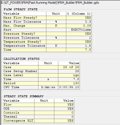
- If we compare the time taken to complete the simulation in FRM model.FRM took more time, but the more time taken by the FRM is because of number of periods for which the simulation is run. FRM is run for 130 periods and time taken for same is 7.8 sec.
- Comparing the cpu time even after running 130 periods of simulation FRM took only 35.10 min.
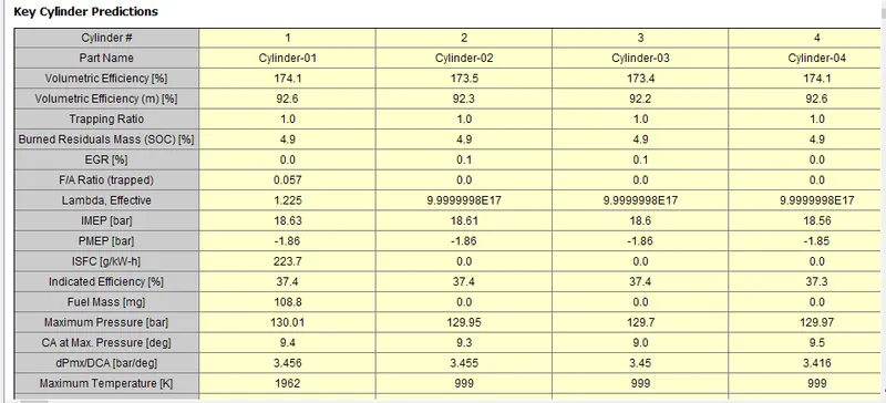
Cylinder_Details
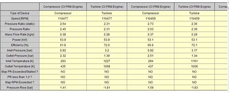
Turbine_Compressor_Results:
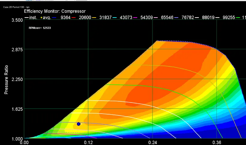
Compressor-Efficiency:
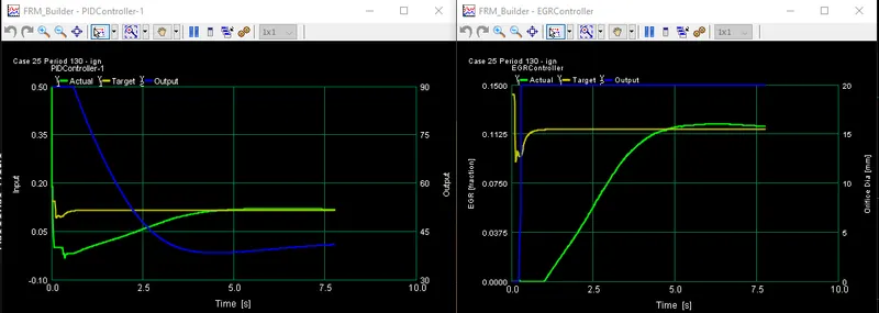
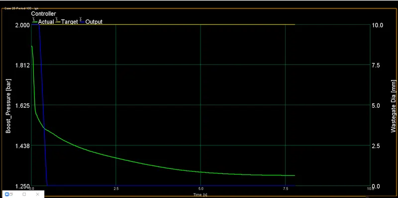
Controller:
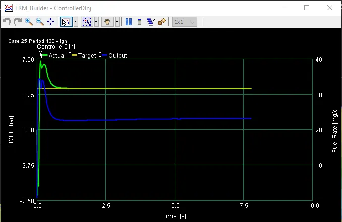
Controller Direct Injection:
EGR_PID_Controller: