Converting a detailed engine model to a FRM model
Aim:
Converting a detailed engine model to a FRM model
Objective:
- Explore tutorial number 9 and write a detailed report
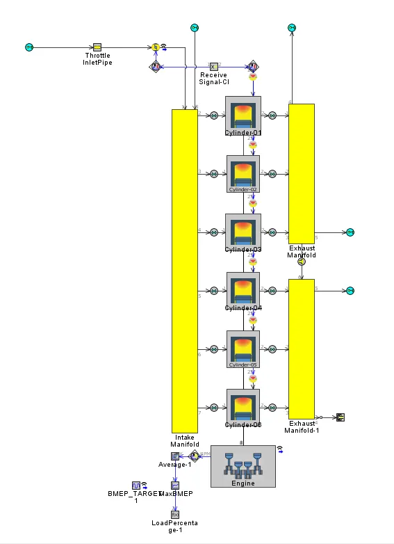
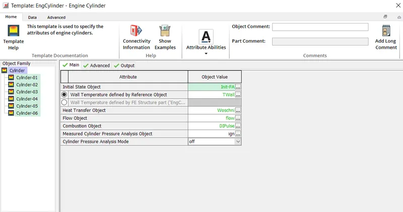
- Build FRM Model for following configuration using FRM builder approach
- Bore 102 mm stroke 115 mm CR 17
- No of cylinder 6
- CI engine
- Twin Scroll Turbine
- GT Controller
- Run all cases
Theory:
FRM are dynamic fully physical engine that are designed specifically to run faster. While high fidelity engine models are common place in the engine performance department, they are often too slow running to incorporate into system level model where using transient event may be simulated, or where the simulation model must respond faster than real time such as HiL simulation model.
When simulation speed is of priority, high fidelity GT power engine model can be simplified into FRM using standard procedure. FRM are used to achieve fast run times in two ways:
- Increasing the simulation time step size
- Decreasing the no of calculation per time step.
Tutorial 9:
This tutorial covers the process of converting detailed, high fidelity engine model into a real time fast running model.
Simulation model:
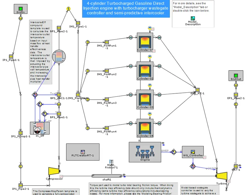
The model is 4-cylinder 4 stroke turbocharged direct injection gasoline engine. Turbine waste gate is being controlled to achieve target BMEP.
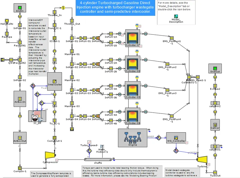
FRM conversion model steps:
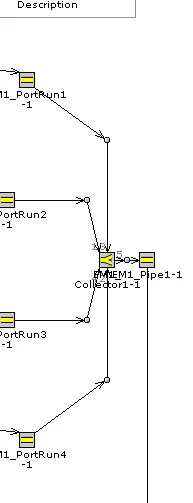
Exhaust manifold
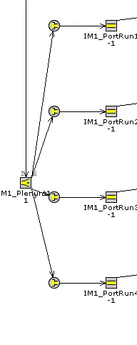
Intake manifold
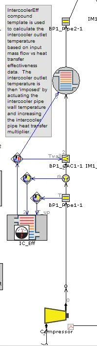
Compressor outlet pipe
Intake pipe

Exhaust port
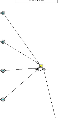
Real time solver
FRM model build:
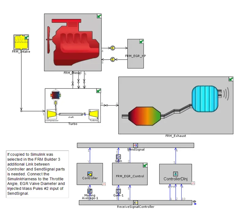
FRM Sub system model:
FRM diesel
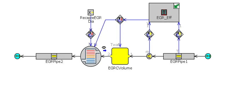
FRM EGR HP
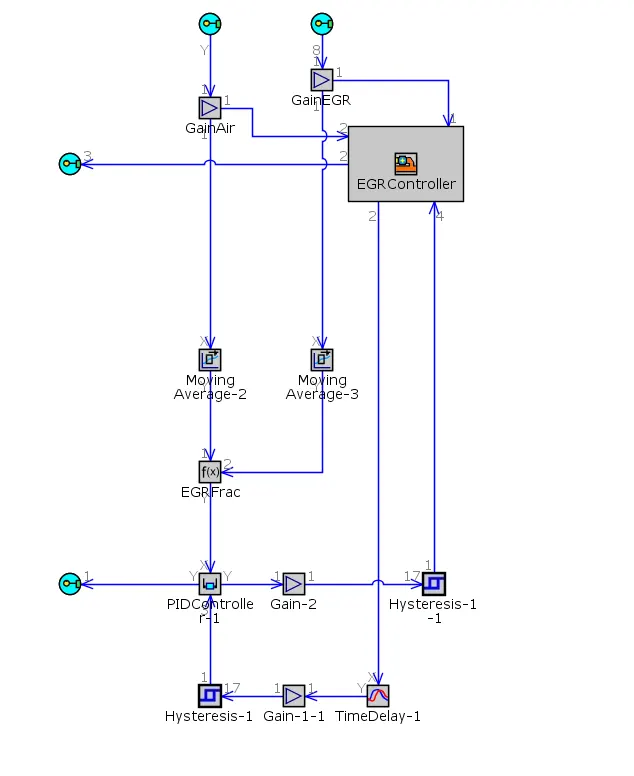
FRM EGR CONTROL
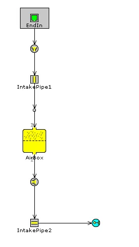
FRM INTAKE
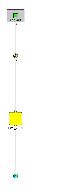
FRM EXHAUST
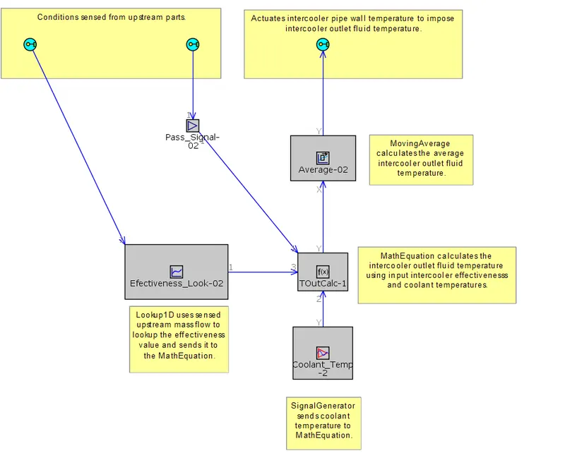
IC EFF
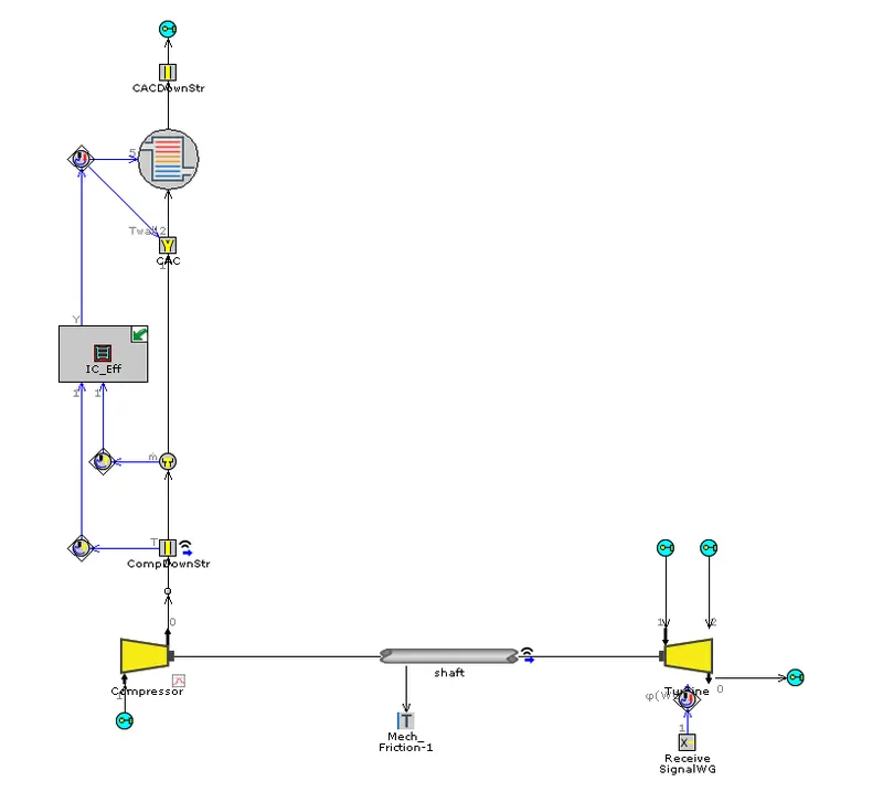
TURBO
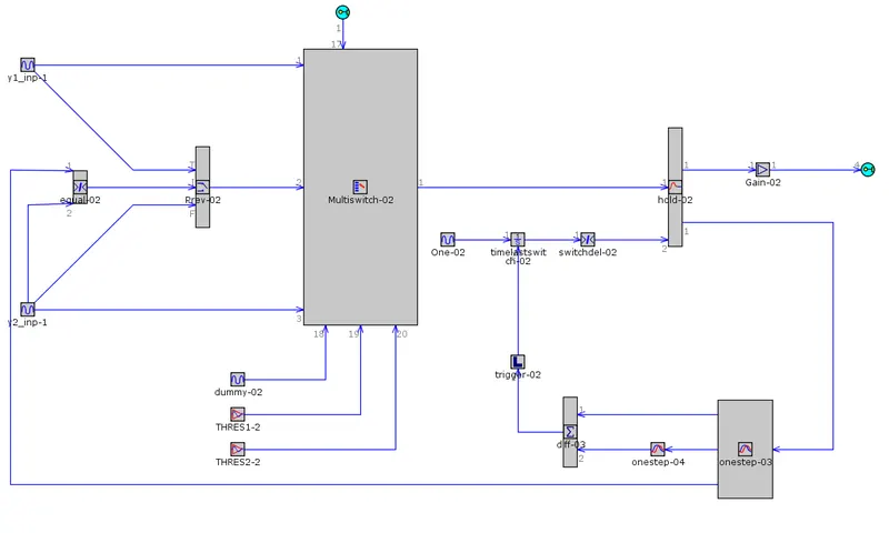
HYSTERISIS LOOP 1
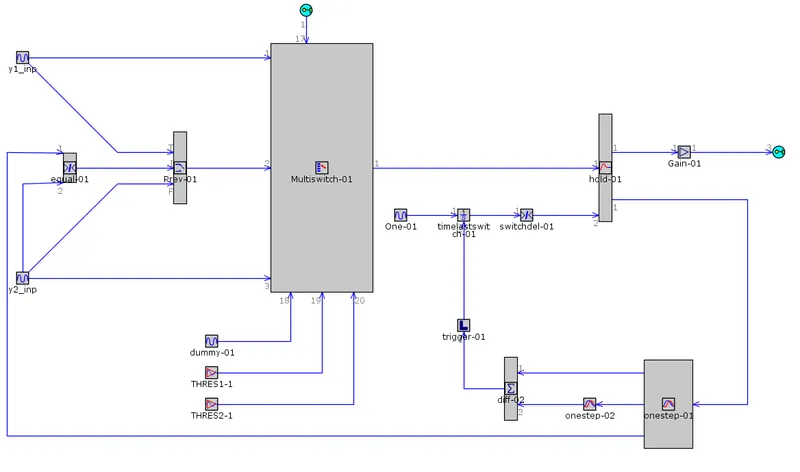
HYSTERISIS LOOP 2
Boundary conditions:
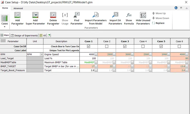
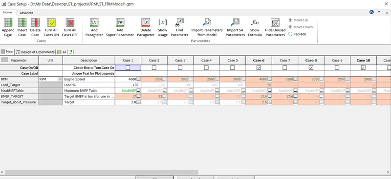
Cylinder slaving conditions
Case setup 1 as a function of rpm and BMEP
Case setup 2 as a function of rpm and BMEP
GT POST:
Case 1:
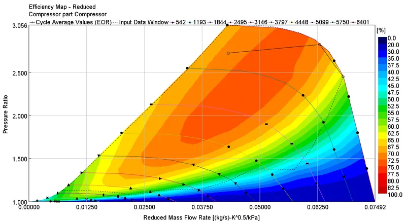
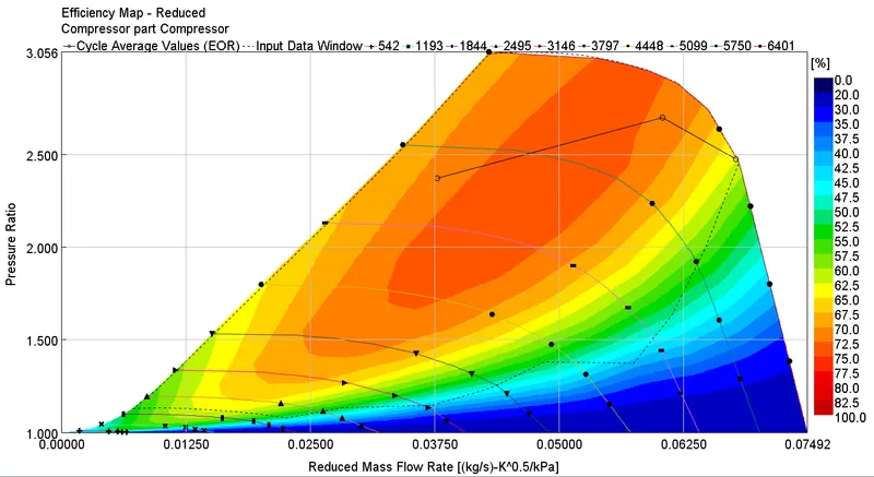
Compressor efficiency map
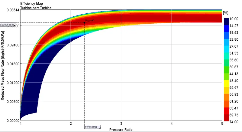
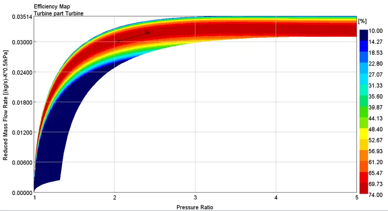
Turbine efficiency map
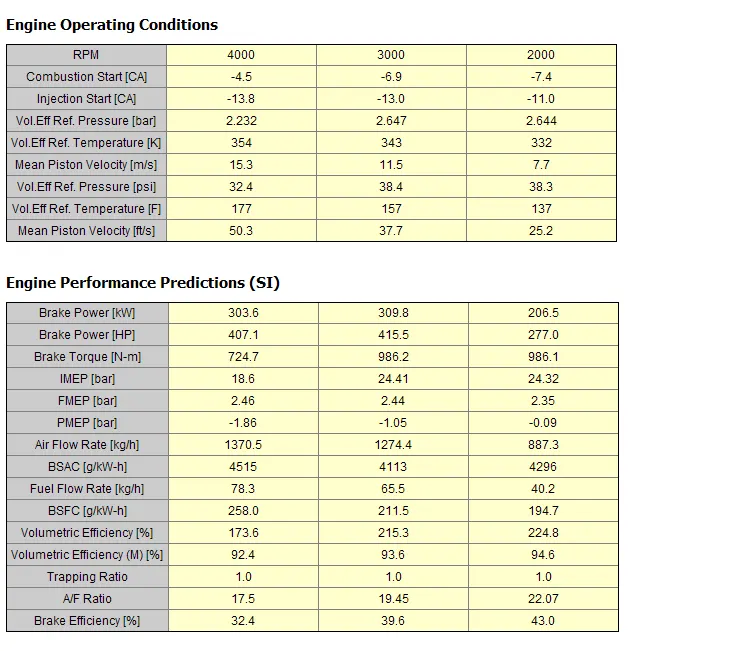
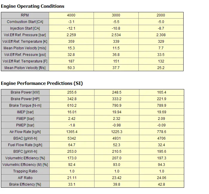
Engine performance
Turbine and compressor performance
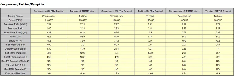
In this case we see that compressor efficiency reaches the best design point at lowest rpm with same BMEP target. The first two design points lies in the excess rotor speed and choke region. Therefore, we should avoid these points. Also, from engine performance data we find A/F ratio is very less in case of high rpmwhich ensures improper burning and high pollutants.
Case 2:
Compressor efficiency map
Turbine efficiency map
Engine performance
Turbine and compressor performance
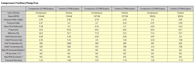
In this case, we find the same pattern as for case 1 only difference is that the efficiency at the best design point is better than the former one. Also due to less BMEP target, low rpm speed can run quiet efficiently compared to high rpm speed.
Conclusions:
- With FRM model builder approach the specific engine design is modelled successfully.
- GT post simulation results shows that with low target BMEP and low rpm level falls on the best design efficiency region of the compressor map.
- FRM model reduces the computational time drastically as compared to normal simulation run time model.