Week-7 Challenge: DC Motor Control
AIM : 1.To run MATLAB demo ‘Speed control of a DC motor using BJT H-bridge' and to modify the model such that armature current doesn’t shoot up when motor changes direction from forward to reverse.
2.To compare ‘The Four-Quadrant Chopper DC Drive (DC7) block’ and H-bridge model.
3.To make a suitable EV model using DC7 block and make result report.
SOLUTION :
1. * Open simulink help and search for the BJT-H bridge model .
* The model is used to control speed of DC motor by changing current and voltage accordingly.
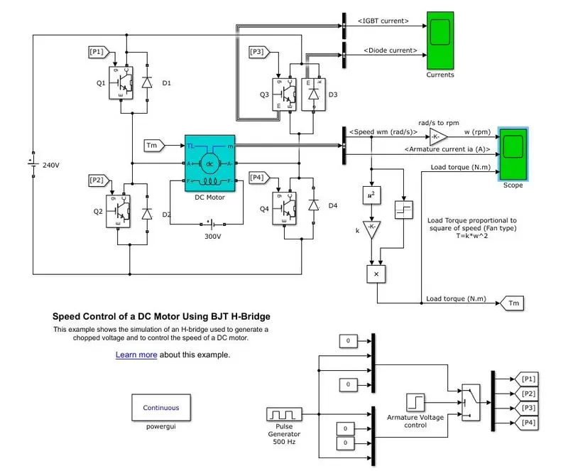
fig1
* In the given model we could see 4 transistors, Q1Q2Q3Q4 and 4 diodes,D1D2D3D4.
* A 240v DC source is applied.
* A transistor is a semi conductor device which is used for both conducting and insulating current or voltage.
* In transistors , C,E&G denotes collector,emitter and ground. All transistors have common emitter here which means current in collector and ground combine and flow through it.
* There are two types of configuration used PNP and NPN where PNP is forward bias and holes be the charge carriers & NPN be reverse bias and electrons be charge carriers but current isnt produced in NPN configuration. To overcome this we use BJT , Bipolar Junction Transistor.
* N represents electrons and P represents positive charge carriers holes.
* In BJT , both electrons and holes be charge carriers. Conduction takes place in both forward and reverse bias.
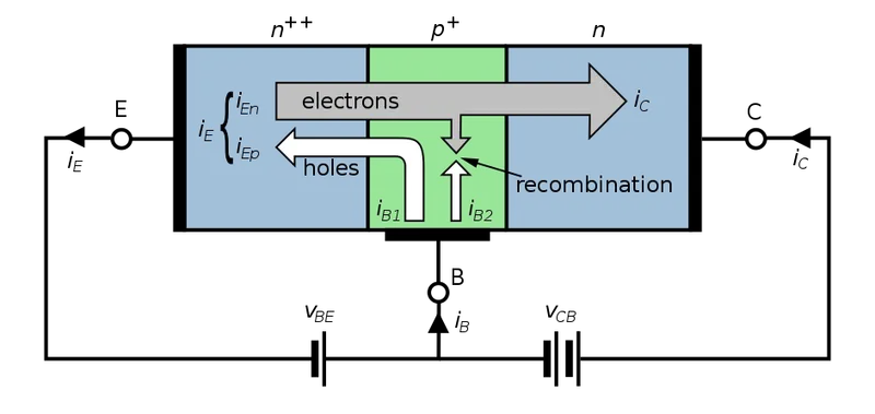
fig2
* In forward bias P type region is connected with positive terminal and N region is connected with negative terminal. In reverse bias it is opposite to forward bias where P region - (-) & N region - (+) . In bjt N is connected with negative terminal of source and another N connected with positive terminal. Vbe represent base voltage which we have given and Vcb represent collector voltage. Now holes in P region flows towards negative terminal of source be and in negative region which is in emitter , the electrons flows towards Vcb as voltage is higher than Vbe. The current flows opposite to the direction of conventional current.
* BJT is current driven.
* In the given model BJT-H bridge model in fig 1 IGBT block is used which is Insulated Gate Bipolar Transistor.
It is combination of BJT and MOSFET. MOSFET stands for Metal Oxide Semiconductor Field Effect Transistor. It is a voltage driven transistor where gate is insulated. This makes IGBT block to be efficient to control electric output. In this system (fig1),when Q1 and Q4 are fired positive voltage is applied to the motor and Q3&Q2 remain closed. The motor is driven is poitive direction with given drive cycle of 75 % .When Q2&Q3 are fired negative voltage flows and polarity changes and motor runs in reverse direction.
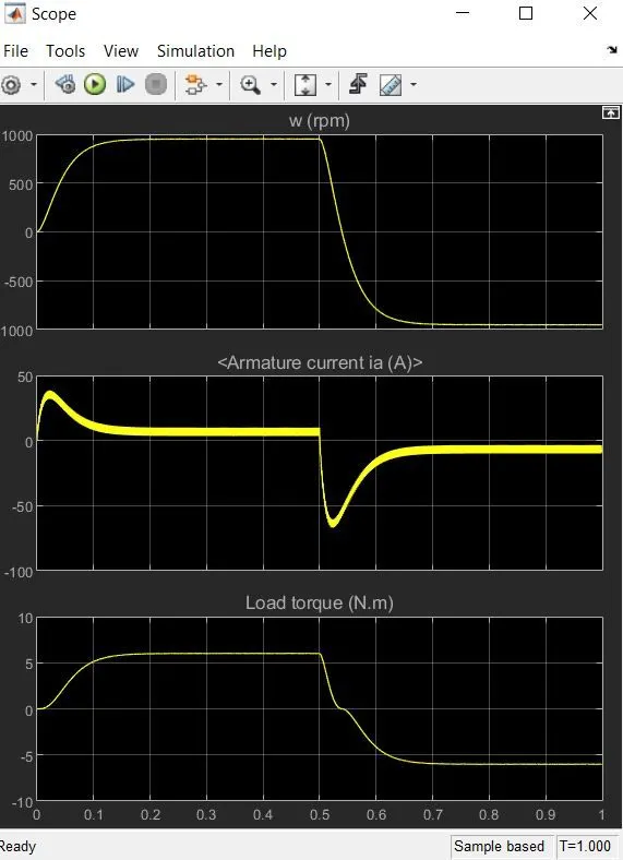
fig3 ( graph of motor speed,armature current and load torque)
* To overcome shooting of armature current when direction of motor is reversed , we could reduce pulse width 75 to 50 or 40 which will mean the drive cycle motor be 40-50%.
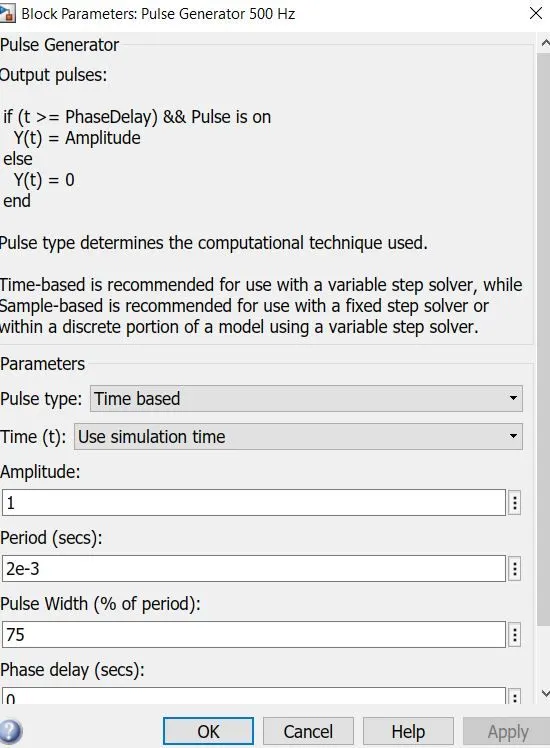
fig4
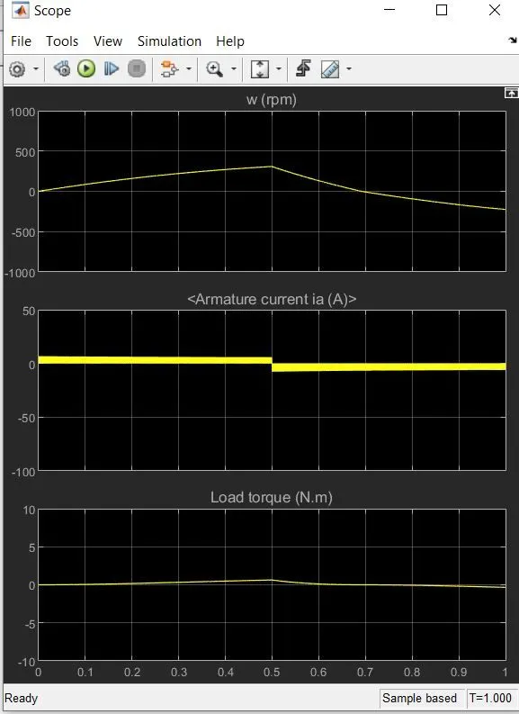
fig5 (when drive cycle is made as 40%)
2. * The chopper is used to convert fixed DC into variable DC
* A DC voltage source is used to drive motor in four quadrant chopper. The system consists of 4 choppers. The system controls speed of motor.
* IGBT is used to provide voltage and current in armature.
* The system operates in 4 quadrants. First is forward motoring , second is forward braking , third is reverse motoring and fourth is reverse breaking. forward motoring denotes clockwise direction and reverse represents anti clockwise direction.
* The image given below represents circuit diagram of H bridge.
* Here when Q1 and Q4 are fired positive voltage is applied to the motor and Q3&Q2 remain closed. The motor is driven is poitive direction with given drive cycle of 75 % .When Q2&Q3 are fired negative voltage flows and polarity changes and motor runs in reverse direction.
DIffERENCES : * DC four quadrant is used in automobiles and BJT is used in electro chemical devices and also in robotics.
* DC consists of PI current controller while in BJT it is not present
* The direction of motor is reversed based on speed reference in DC7 where as in BJT duty cycle is used.
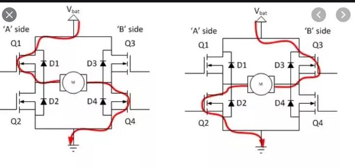
fig - H bridge circuit.
3. * Search for DC7 block and open using simulink.
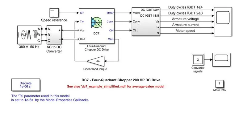
fig6
*From the above block some of the blocks are replaced based on drive cycle.
* A DC voltage source is given as input power.
* Linear load torque block is replaced with respect to torque characteristic equation T=24.7+0.0051w2
where w is motor speed.
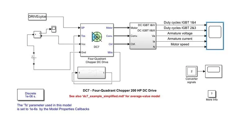
fig7
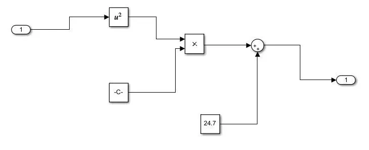
fig8
*Drive cycle is made in an excel sheet and it is imported to matlab .
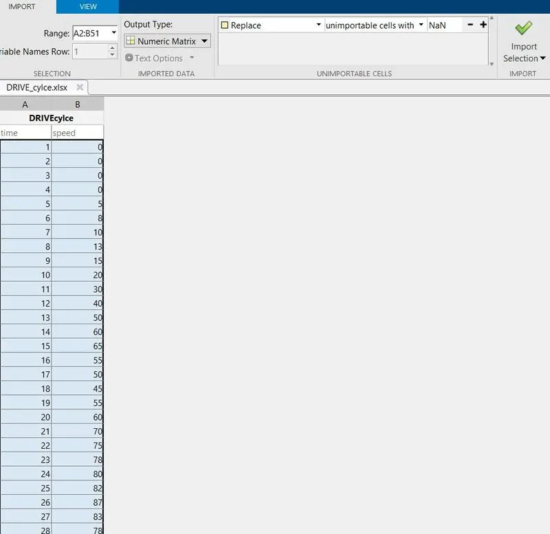
fig9
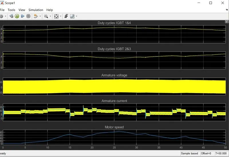
fig10 ( results obtained after running the system. IGBT 1&4 represents forward direction and 3&2 represents reverse direction of motor. According to speed the variation in voltage and current takes place.)