Week-7 Challenge: DC Motor Control
Q.1
Model-
Pulse Generator-
A). Working of H-Bridge Model:
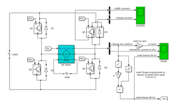
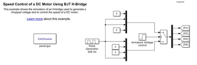
The H-bridge DC chopper circuit is crafted to regulate the motor's speed. In this setup, IGBTs function similarly to BJTs in power-switching applications. Four IGBT switches are employed to invert the supplied DC voltage ranging from 0 to 240 volts. Current travels from the collector (C) to the emitter (E). The gate signals, determined by the pulse generator based on the motor's armature voltage, govern the operation of these switches.
This image depicts the voltage progression from start to finish during each step time interval. The IGBT switches are controlled by pulses, with four switches labeled as Q1, Q2, Q3, and Q4, corresponding to pulses P1, P2, P3, and P4, respectively.
In the first state, Q1 and Q4 are activated with a 1V signal applied to the IGBTs, allowing current from the battery to flow through Q1 and Q4. Diodes D2 and D3 serve as freewheeling diodes in this state, facilitating forward motoring and braking.
In the second state, Q2 and Q3 are activated using a 1V signal, enabling current flow through Q2 and Q3. Diodes D1 and D4 act as freewheeling diodes in this scenario, supporting reverse motoring and braking. The current direction reverses in this state.
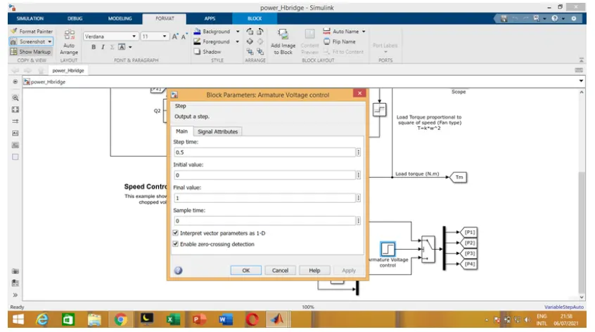
Both states occur within a 0.5-second sample time, allowing for the conversion of DC supply to feed the motor's armature. Freewheeling diodes are utilized in the circuit for safety purposes, protecting against low current flow feedback and voltage fluctuations.
During motor operation, the armature terminals are linked with a 240V supply through the inverter circuit, while the field windings are connected to a 300V DC supply to function as an electromagnet for the motor. The load torque is applied as mechanical input to the motor for reference.
Consequently, the magnetic fields generated cause the rotor armature's variable current-carrying conductors to experience forces according to Fleming's left-hand rule, initiating motor rotation. Run the demonstration model and analyze the results obtained from scopes.
Result:
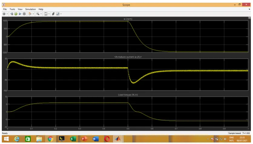
Speed of motor:
-Initially increases to 0 to nearly 900 rpm upto 0.5 secs(Forward motoring action takes place).
-Then speed reduces to 0 rpm(Forward dynamic breaking action takes place).
-Then speed increases from 0 to -900 rpm at upto 1 sec( Reverse motoring action takes place).
-Then reverse dynasmic breaking occurs(Not shown in scope).
Load torque of motor:
-Initially torque increase from 0 to 0.5 secs in forward motoring action.
-Then torque reduces to 0 Nm in forward dynamic breaking mode.
-Then torque increases in reverse direction in reverse motoring action upto 1 sec.
-Again torque reduce to zero.(Not shown in scope).
B). Armature current shoot up in motor.
Here the initial current shoot up is due to sudden increase in voltage which inurns regulated by duty cycle.In this case motor driven in 75% of duty cycle.(i.e) 0.75*240= 180 V.
We can change the duty cycle to 50%(120 V) and seen the results as,
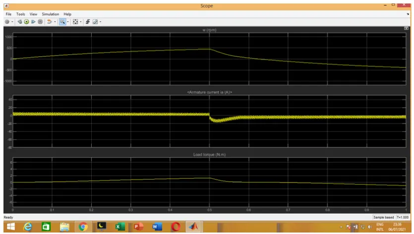
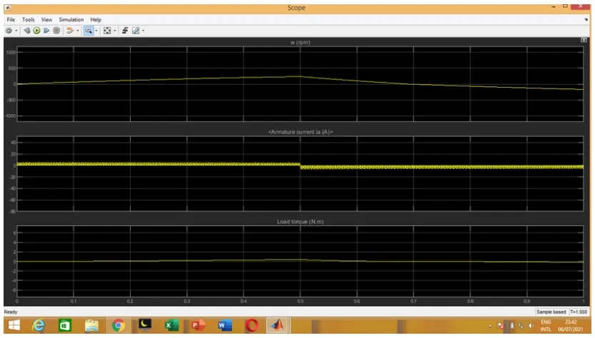
Conclusion:
Thus to reduce the shootup armature currents we have to change the duty cycle gradually from 0 to 100%,that inturns increases voltage gradually and speed also changes accordingly.
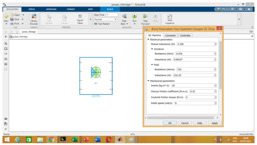
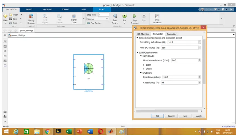
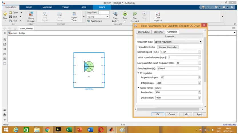
Connection:
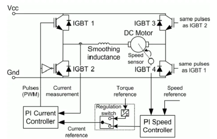
Inputs and outputs:
Armature voltage ,speed referance ,motor torque referance are given as inputs.
Motor,convertor,controller,motor angular speed are get as outputs.
Working:
In this setup, four IGBT switches are utilized. Pulses are generated from the current controller (PI controller), which adjusts the pulses by comparing the measured armature current with the current reference. The current reference can be generated using a regulation switch, incorporating torque reference and PI speed controller pulses, which are internally compared with the motor speed and the reference speed provided as input.
Primarily, speed control is managed by the current controller. This arrangement allows for four-quadrant operations:
1. Forward motoring mode and forward regenerative braking mode: Q1 and Q4 are activated while Q2 and Q3 are deactivated.
2. Reverse motoring mode and reverse regenerative braking mode: Q2 and Q3 are activated while Q1 and Q4 are deactivated.
Q.2
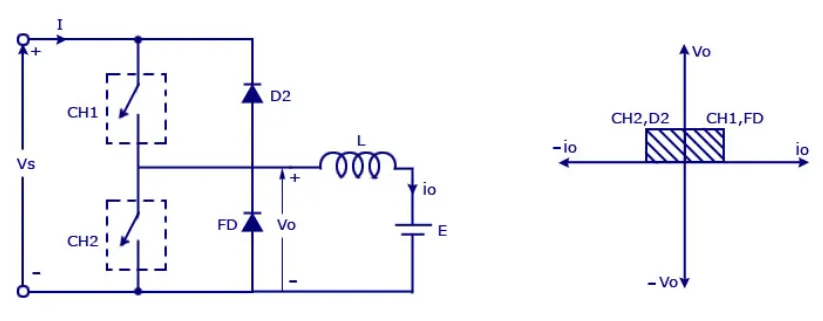
Chopper Model:
Where,
Vs=DC voltage source.
CH1= Power electronic switch 1.
CH2= Power electronic switch 2.
D2,FD = Free wheeling diodes.
L=Inductor load.
E Back emf from the load.
Mode of operation:
-Here either one should be ON at a time,either CH1 or CH2.
-If CH1 is ON the current flows from source +ve to load(here DC motor),passes through L and E to -ve terminal of -source.(1st quadrant)
-If CH1 is OFF the, FD diode conducts and complete the circuit (L-E-FD-L) as stored energy in inductor L.The voltage across is also positive voltage,current direction also positive.
-Now If CH2 is ON,Current flow from E(Load current) completes the circuit(L-CH2-E).
-If CH2 gets OFF,the current passes through D2 towards source completes the circuit(E-L-D2-+ve source- -ve source-E).
-In this stage regenerative breaking occurs.(2nd quadrant).
-This cycle continuous again upto stop time.
Working:
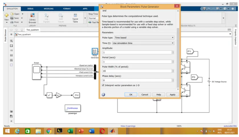
Result:
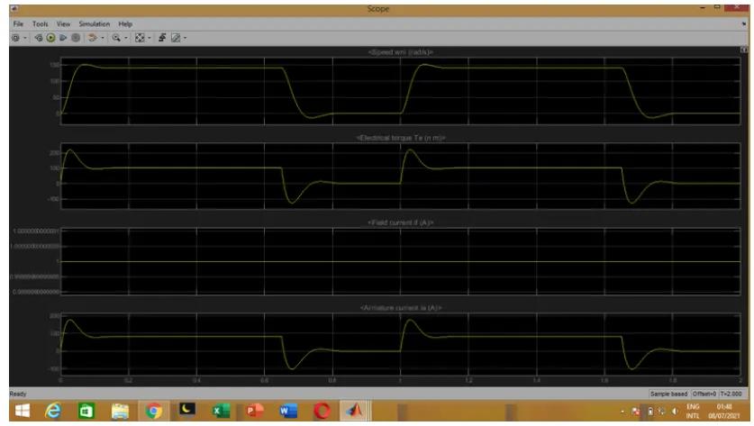
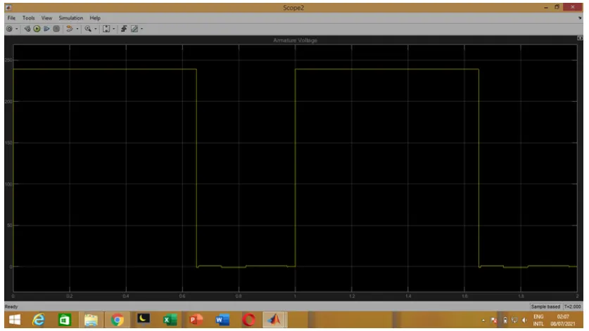
The result scope shows,
Speed increases in first quadrant as forward motoring action.Current is in positive direction.
Speed reduces at OFF time, So current get set back to source as regenerative breaking mode when CH2 open up.
Torque changes according to the speed crossing zero and produce negative torque while in second quadrant.
Thus result get justified.
Q.3
BLDC motor named as brushless dc motor having high effenciency than other types of motors.This motor is also known to be synchronous motor.
Many motors traditionally incorporate brushes within their rotors to facilitate current transfer. However, in this case, the rotor is uniquely equipped with permanent magnets.
The stator, comprising wound coils, remains stationary while generating variable DC voltages to rotate the permanent magnet by continuously altering the magnetic field of the stator poles.
Motor control is achieved by adjusting the magnitude and direction of the current flowing through the stator windings.
In a BLDC motor equipped with three coils on the stator, there are six electrical wires (two per coil), with three wires typically internally connected within the motor body. The remaining three wires extend from the motor body. Wiring in a BLDC motor is more intricate than simply connecting the positive and negative terminals of a power cell. We will delve deeper into the workings of these motors in the subsequent sessions of this series.
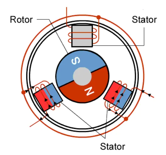
Operation of BLDC Motor:
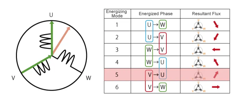
The three winding terminals, labeled U, V, and W, are connected at a single point, forming a configuration where the angle between two coils is set at 120 degrees.
When current flows from terminal U to terminal W, it magnetizes the coils, attracting the rotor—comprising a permanent magnet—to align with the resultant arrow, indicated above. In this configuration, the north pole of the magnet aligns with the arrow mark of the resultant arrow.
To maintain rotation, it's essential to continuously alternate the flux, ensuring that the permanent magnet consistently follows the rotating magnetic field induced by the coils. This involves continuously switching the energization of terminals U, V, and W to keep the resultant flux in motion, thereby creating a rotating field that exerts a continual pull on the rotor magnet.
However, this process can result in slight discontinuities in rotation, leading to motor vibration and noise. To achieve smooth, continuous rotation of the rotor, it's necessary to control the current flow through all three poles simultaneously.
As depicted below, continuous changes in current flow in all stator poles simultaneously with a 120-degree phase shift can be achieved to ensure smooth, continuous rotation.
Control of BLDC Motor:
The control of a BLDC motor involves utilizing the inverter circuitry to regulate the voltage applied to each coil, thereby controlling the current magnitude.
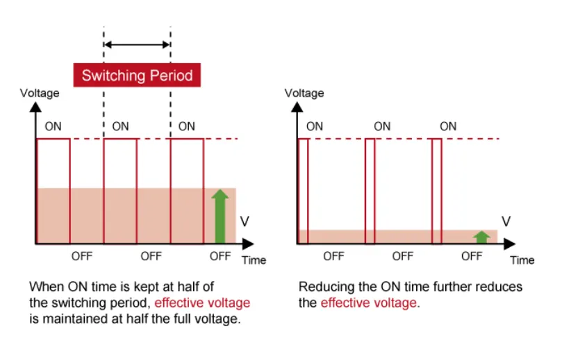
One common method for voltage adjustment is through pulse width modulation (PWM). This technique involves modifying the voltage by extending or reducing the duration of the pulse ON time. The duty cycle, which represents the ON time as a ratio of the total ON+OFF switching interval, determines the extent of voltage adjustment. Increasing the duty cycle is equivalent to raising the voltage, while reducing the duty cycle is akin to lowering the current.
Implementing PWM can be accomplished using microprocessors (MPUs) equipped with dedicated PWM hardware. While 120-degree conducting control only necessitates two-phase voltage control, sinusoidal control requires three-phase voltage control and is significantly more complex. Hence, appropriate inverter circuitry is crucial for effectively driving BLDC motors.