Week-7 Challenge: DC Motor Control
1. A. Explain a MATLAB demo model named ‘Speed control of a DC motor using BJT H-bridge’.
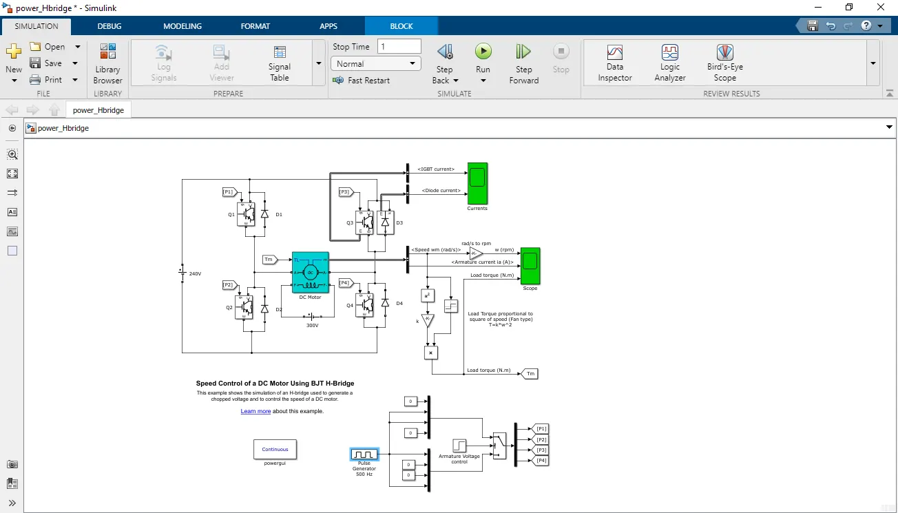
A. The MATLAB demo model named 'Speed control of a DC motor using BJT H-bridge' is a simulation model that demonstrates the speed control of a DC motor using a BJT H-bridge circuit. The model consists of a DC motor, a BJT H-bridge circuit, and a closed-loop control system that regulates the speed of the motor. The H-bridge circuit consists of four transistors that are used to switch the polarity of the voltage across the motor. The closed-loop control system uses a PI controller to adjust the duty cycle of the PWM signal that drives the H-bridge circuit, based on the difference between the desired speed and the actual speed of the motor. The model can be used to understand the working of the BJT H-bridge circuit and closed-loop control systems for DC motor speed control.
B. Comment on the armature current shoot-up from the scope results.
The armature current shoot-up from the scope results in the BJT H-bridge model due to the inductive nature of the DC motor. When the transistor switches in the H-bridge circuit turn on or off, a high voltage is induced in the motor windings due to the sudden change in current. This causes a transient overvoltage that results in a sudden increase in the armature current. This effect is more pronounced at higher switching frequencies and can cause issues such as voltage spikes, noise, and EMI. To mitigate this effect, snubber circuits or freewheeling diodes are often used.
The Bipolar Junction Transistor (BJT), when used for power-switching applications, operates as an IGBT. When it is being conducted (BJT operating in the saturated region), a forward voltage Vf is developed between the collector and emitter (in the range of 1 V). Therefore, the IGBT block can be used to model the BJT device.
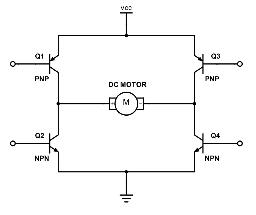
The H-bridge consists of four BJT/Diode pairs (BJT simulated by IGBT models). Two transistors are switched simultaneously: Q1 and Q4 or Q2 and Q3. When Q1 and Q4 are fired, a positive voltage is applied to the motor, and diodes D2-D3 operate as free-wheeling diodes when Q1 and Q4 are switched off. When Q2 and Q3 are fired, a negative voltage is applied to the motor, and diodes D1-D4 operate as free-wheeling diodes when Q2 and Q3 are switched off.
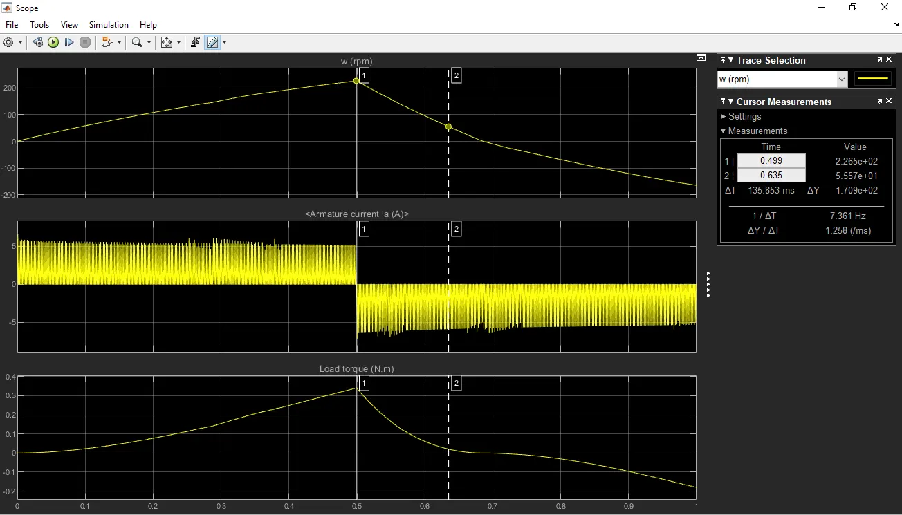
Scope after running the default model to examine the 'shoot up' in armature current when the poles are reversed.
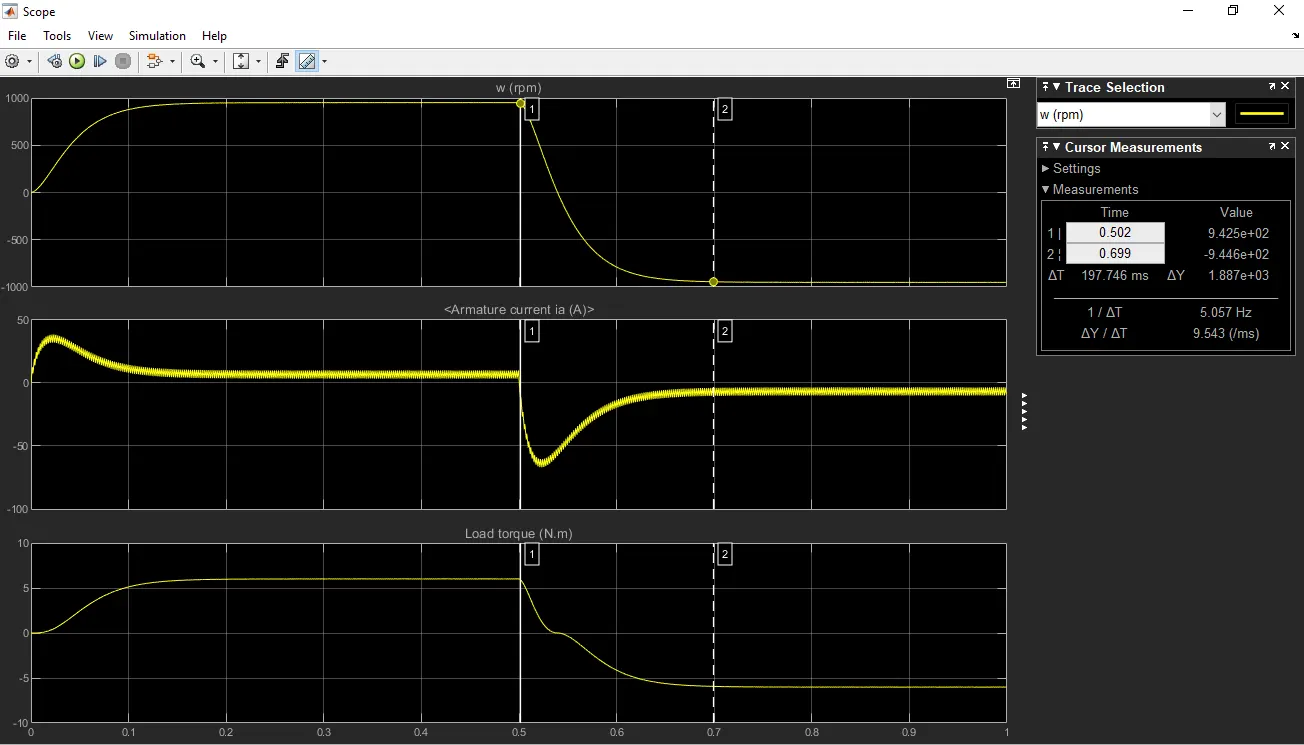
The motor starts in a positive direction with a duty cycle of 75% (mean DC voltage of 180V). At t= 0.5 sec., the armature voltage is suddenly reversed and the motor runs in a negative direction.
'Scope' shows motor speed, armature current, and load torque, and 'Currents' shows currents flowing in BJT Q3 and diode D3.
Refer to the help section of ‘The Four-Quadrant Chopper DC Drive (DC7) block’. Compare it with the H-bridge model.
The Four-Quadrant Chopper DC Drive (DC7) block is a Simulink block that provides a model of a four-quadrant chopper DC motor drive. The block includes an H-bridge circuit with four switches that are used to control the direction and speed of the motor. The block also includes a control system that regulates the motor speed using a PI controller. The key difference between the DC7 block and the BJT H-bridge model is that the DC7 block is a four-quadrant chopper, which means it can control the motor speed in both forward and reverse directions. Additionally, the DC7 block includes protection features such as overvoltage, overcurrent, and overtemperature protection, which are not present in the BJT H-bridge model.
A 2-quadrant chopper is a DC motor control circuit that can operate the motor in two quadrants, i.e., the first and the fourth quadrant. The circuit consists of a power supply, a chopper circuit, and a DC motor. The chopper circuit consists of a switch, a diode, and an inductor, and is used to regulate the motor speed by varying the duty cycle of the switch. When the switch is turned on, the motor is connected to the power supply, and the current flows through the motor. When the switch is turned off, the current flows through the diode and the inductor, and the motor generates a back EMF.
To develop a 2-quadrant chopper using Simulink, follow the steps below:
Open Simulink and create a new model.
Drag and drop a DC motor block, a switch block, a diode block, and an inductor block onto the model.
Connect the motor block to the switch block, the diode block, and the inductor block as shown in the figure below.
Double-click the switch block to open its block parameters and set the pulse width modulation (PWM) frequency and the duty cycle as desired.
Run the simulation and observe the motor speed and current waveforms.
The working of the 2-quadrant chopper can be explained as follows: When the switch is turned on, the motor is connected to the power supply and the current flows
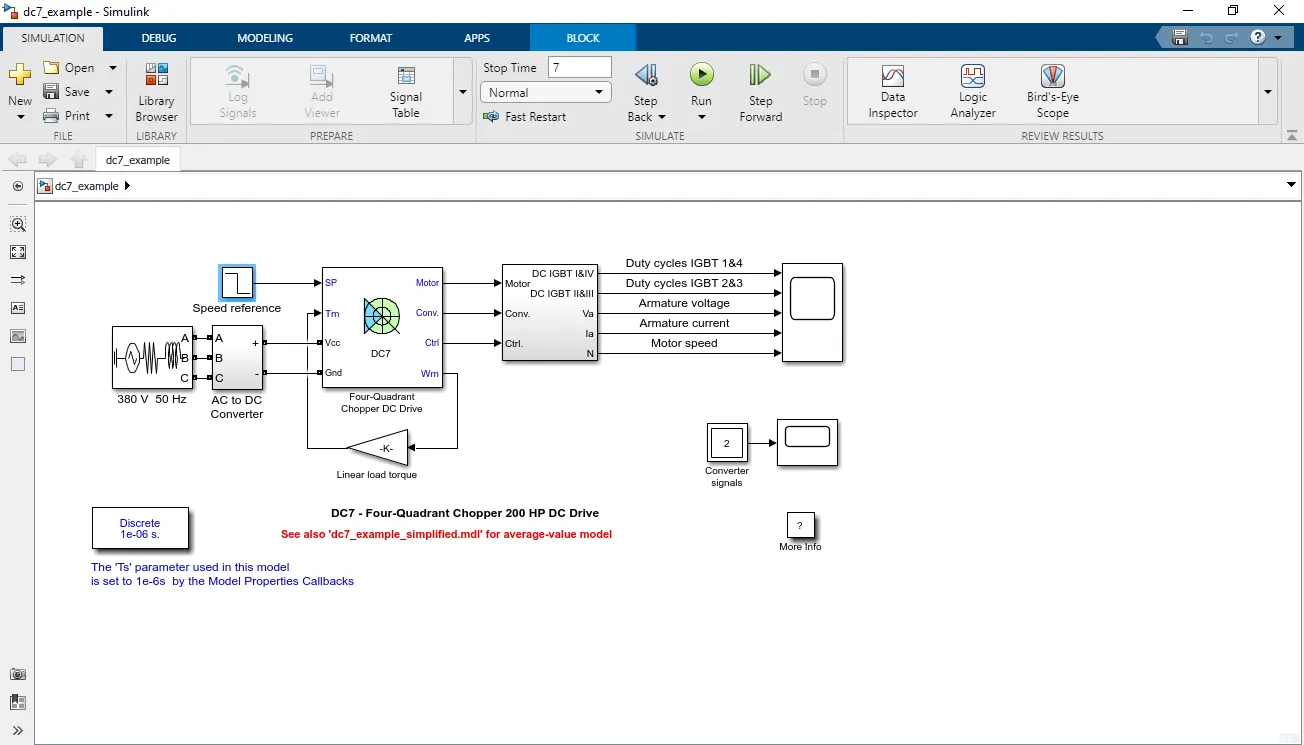
Refer to the help section of ‘The Four-Quadrant Chopper DC Drive (DC7) block’. Compare it with the H-bridge model.
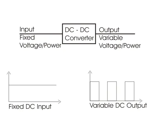
A chopper is a DC-DC converter circuit. It will convert a fixed DC into Variable DC.
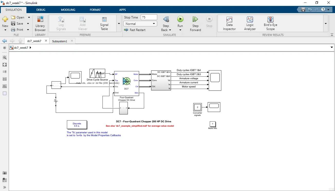
DC7 chopper circuit:
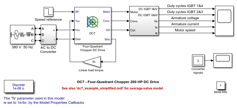
The 200 HP DC motor is separately excited with a constant 150 V DC field voltage source. The armature voltage is provided by an IGBT converter controlled by two PI regulators. The converter is fed by a 515 V DC bus obtained by rectification of a 380 V AC 50 Hz voltage source. To limit the DC bus voltage during dynamic braking mode, a braking chopper has been added between the diode rectifier and the DC7 block.
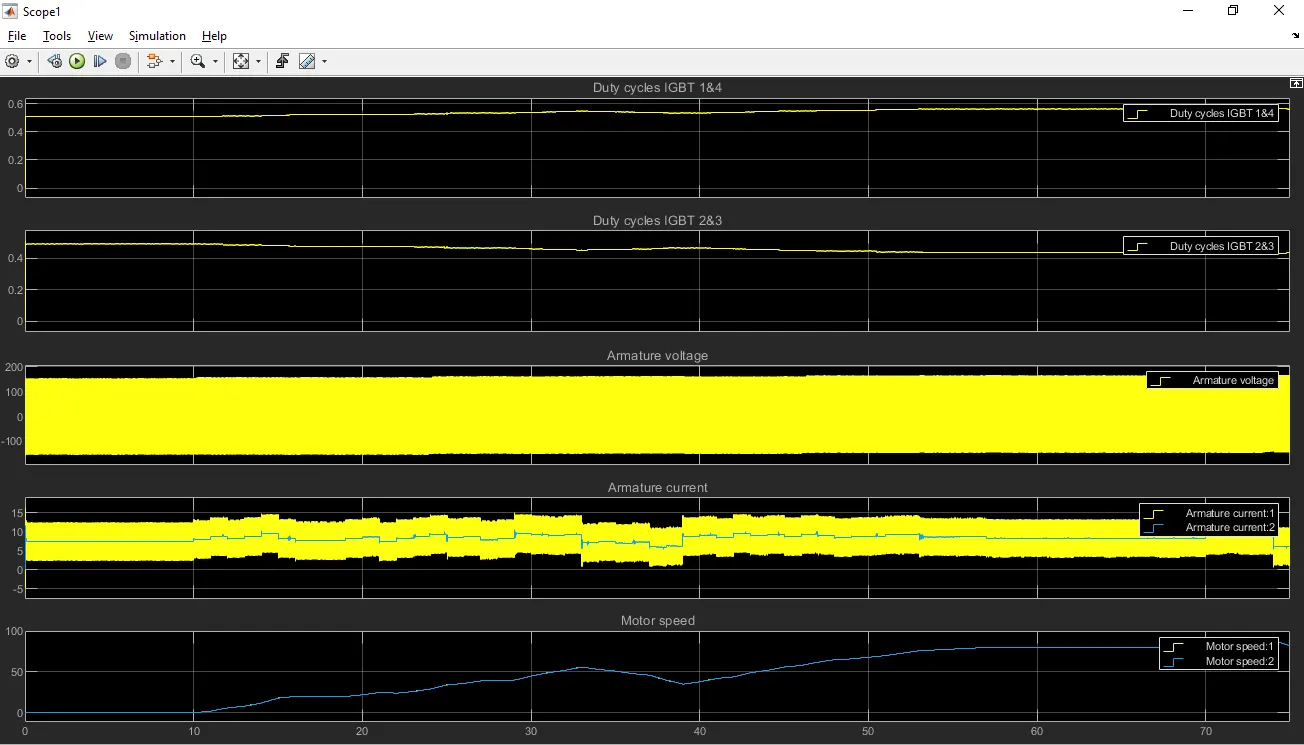
The first regulator is a speed regulator, followed by a current regulator. The speed regulator outputs the armature current reference (in p.u.) used by the current controller to obtain the electromagnetic torque needed to reach the desired speed. The speed reference change rate follows acceleration and deceleration ramps to avoid sudden reference changes that could cause the armature to over-current and destabilize the system. The current regulatory controls the armature current by computing the appropriate duty ratios of the 5 kHz pulses of the four IGBT devices (Pulse Width Modulation). For proper system behavior, the instantaneous pulse values of IGBT devices 1 and 4 are opposite to those of IGBT devices 2 and 3. This generates the average armature voltage needed to obtain the desired armature current. To limit the amplitude of the current oscillations, a smoothing inductance is placed in series with the armature circuit.
H-BRIDGE
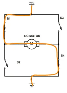
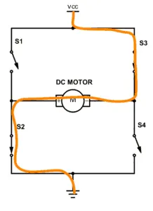
An H-bridge is a simple circuit that lets you control a DC motor to go backward or forward.
If you close switches 1 and 4, you have plus connected to the left side of the motor and minus to the other side. And the motor will start spinning in one direction.
If you instead close switch 2 and 3, you have plus connected to the right side and minus to the left side. And the motor spins in the opposite direction.
output plot:
Explain in a brief about operation of BLDC motor.
A BLDC (Brushless DC) motor, also known as electronically commutated motor, is a type of synchronous electric motor which uses a permanent magnet rotor and a stator with electronically controlled coils.
The BLDC motor operation is based on the principle of a rotating magnetic field produced by the stator windings, which attracts the permanent magnets on the rotor. The direction of the magnetic field is controlled by the electronic commutation circuit, which switches the current in the stator coils according to the rotor position.
The electronic commutation of the BLDC motor replaces the traditional mechanical commutation system used in DC motors, resulting in a more efficient and reliable motor with higher power density and better speed control.
The operation of a BLDC motor involves three phases:
Commutation phase - the electronic circuit determines the position of the rotor and switches the current to the appropriate stator phase, based on the back electromotive force (EMF) feedback from the motor.
Power phase - the current flows through the stator coils, producing a rotating magnetic field that attracts the permanent magnets on the rotor and causes it to rotate.
Feedback phase - the motor generates back EMF as it rotates, which is sensed by the electronic circuit to determine the position of the rotor and initiate the next commutation phase.
BLDC motors are widely used in various applications such as robotics, electric vehicles, aerospace, and consumer electronics, due to their high efficiency, reliability, and precise speed control.
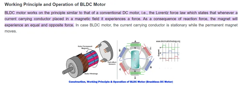
When the stator coils are electrically switched by a supply source, it becomes electromagnet and starts producing the uniform field in the air gap. Though the source of supply is DC, switching makes to generate an AC voltage waveform with trapezoidal shape. Due to the force of interaction between electromagnet stator and permanent magnet rotor, the rotor continues to rotate.
Consider the figure below in which motor stator is excited based on different switching states. With the switching of windings as High and Low signals, corresponding winding energized as North and South poles. The permanent magnet rotor with North and South poles align with stator poles causing motor to rotate.
Observe that motor produces torque because of the development of attraction forces (when North-South or South-North alignment) and repulsion forces (when North-North or South-South alignment). By this way motor moves in a clockwise direction.
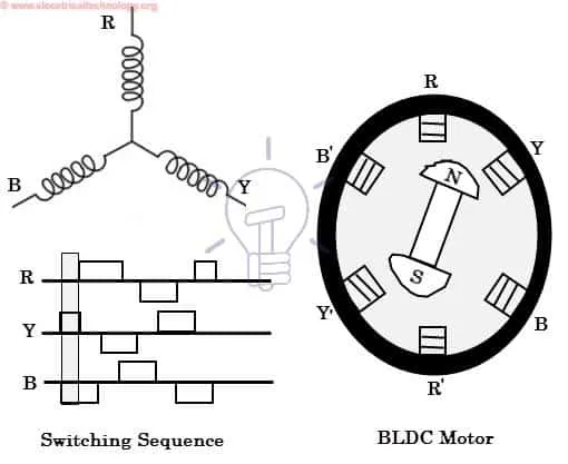
Here, one might get a question that how we know which stator coil should be energized and when to do. This is because; the motor continuous rotation depends on the switching sequence around the coils. As discussed above that Hall sensors give shaft position feedback to the electronic controller unit.
Based on this signal from sensor, the controller decides particular coils to energize. Hall-effect sensors generate Low and High level signals whenever rotor poles pass near to it. These signals determine the position of the shaft.