Week-7 Challenge: DC Motor Control
Aim 1) A. Explain a MATLAB demo model named ‘Speed control of a DC motor using BJT H-bridge’.
- Comment on the armature current shoot-up from the scope results.
- Refer to the help section of ‘The Four-Quadrant Chopper DC Drive (DC7) block’. Compare it with the H-bridge model.
Aim 2) Develop a 2-quadrant chopper using simulink & explain the working of the same with the relevant results. (Refer to article - Multiquadrant operation of motor )
Aim 3) Explain in a brief about operation of BLDC motor.
Ans -
BJT H-Bridge -
A DC motor controller is any device that can manipulate the position, speed or torque of a motor. An H-bridge is a simple circuit, containing four switching elements, with the load at the center, in an H-like configuration. It’s a mature circuit design for controlling a DC motor. It can operate in both motoring and braking modes. Figure below shows a simplified H-bridge circuit.
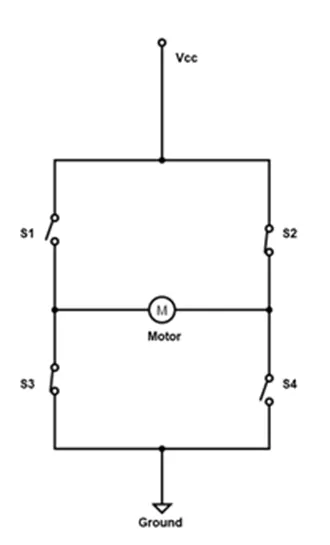
Figure 1: H-bridge circuit for motor control
There are four switches (S1, S2, S3 & S4) and when either two are closed in pairs they complete the circuit and thereby powers the motor. To understand the working look at the figure below-
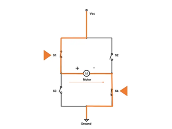
Figure 2: S1 & S4 are closed causes the motor to rotate
Forward motoring-
When switch S1 & S4 are closed the current from Vcc enters the motor from the positive terminal making the motor to work in forwarding mode.
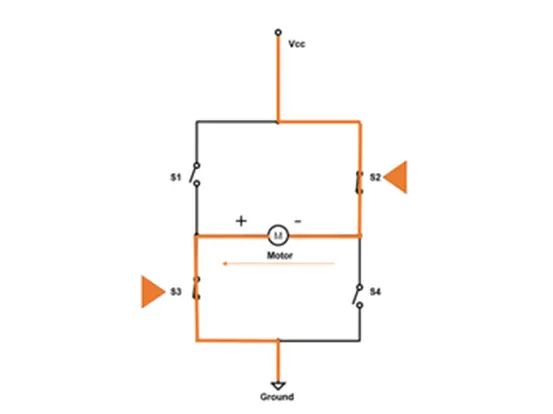
Figure 3: S2 & S3 are closed making the motor to rotate in reverse
Reversed motoring-
When switch S2 & S3 are closed the current from Vcc enters the motor from the negative terminal making the motor to work in reverse mode.
Braking
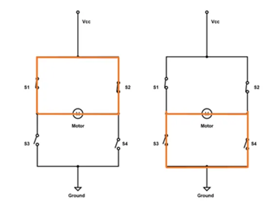
Figure 4: Motor operating in braking mode
When switch S1 & S2 or S3 & S4 are closed the potential difference at both terminals of the load equals nearly the positive supply voltage Vcc and ground voltage respectively, hence there is no current passing through the load and thus the motor slows down itself.
The different modes of operation are summarised in the table below-
|
Switch |
State |
Operating mode |
|
S1 & S4 |
Closed |
Forward motoring |
|
S2 & S3 |
Closed |
Reverse motoring |
|
S1 & S2 |
Closed |
Forward braking |
|
S3 & S4 |
Closed |
Reverse braking |
|
Only one switch |
Closed |
Coasting |
|
S1 & S3 or S2 or S4 |
Closed |
Short-circuit will damage the circuit |
An actual motor controller using BJTs as switches is shown in the figure below-
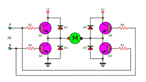
Figure 5: H-bridge motor controller using BJT as switches from ElecCircuit.com
H- Bridge motor controller model-
Now to open the model in MatLab type the command “power_Hbridge” and the model will open in Simulink interface.
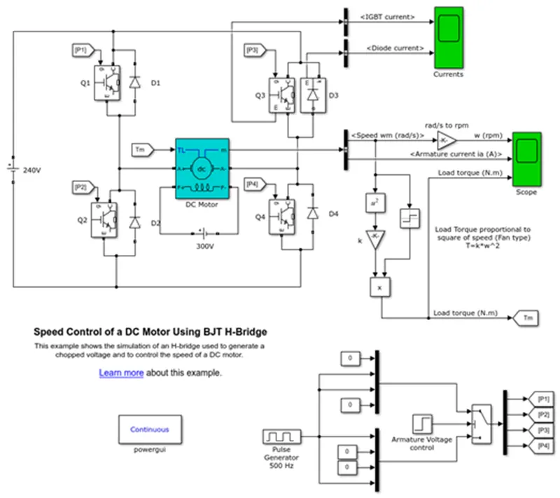
Figure 6: H-bridge motor controller model
The Bipolar Junction Transistor (BJT) when used for power switching applications, operates as an IGBT. When it is conducting (BJT operating in the saturated region), a forward voltage (Vf) is developed between collector and emitter (in the range of 1 V). Therefore, the IGBT block can be used to model the BJT device.
The IGBT block does not simulate the gate current controlling the BJT or IGBT. The switch is controlled by a Simulink® signal (1/0). The DC motor uses the preset model (5 HP 24V 1750 rpm). It simulates a fan type load (where Load torque is proportional to square of speed). The armature mean voltage can be varied from 0 to 240 V when the duty cycle (specified in the Pulse Generator block) is varied from 0 to 100%.
The H-bridge consists of four BJT/Diode pairs (BJT simulated by IGBT models). Two transistors are switched simultaneously: Q1 and Q4 or Q2 and Q3. When Q1 and Q4 are fired, a positive voltage is applied to the motor and diodes D2-D3 operate as free-wheeling diodes when Q1 and Q4 are switched off. When Q2 and Q3 are fired, a negative voltage is applied to the motor and diodes D1-D4 operate as free-wheeling diodes when Q2 and Q3 are switched off. [1]
This Simulink® model works in exact same fashion as H- bridge circuit explained above.
The motor starts in the positive direction with a duty cycle of 75% (mean DC voltage of 180V). At t= 0.5 sec., the armature voltage is suddenly reversed and the motor runs in the negative direction.
'Scope' shows motor speed, armature current and load torque and 'Currents' shows currents flowing in BJT Q3 and diode D3.
When simulating the model with default values we get the following results.
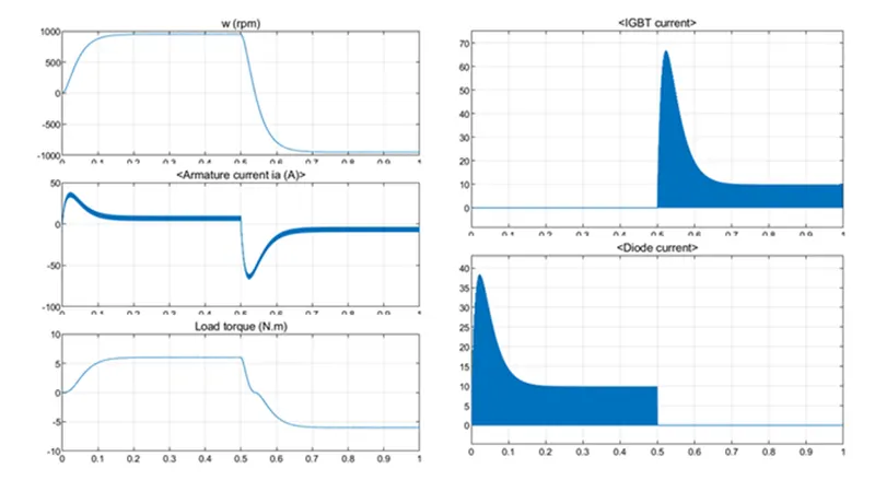
But here we can observe when polarity is reversed the armature current drops significantly and attains a negative value of -66 amps.
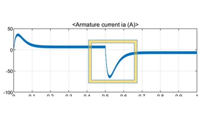
Here we are interested in reducing the initial shoot-up of the armature current. To do so we can Pulse-width modulation.
Pulse-width modulation (PWM) or duty-cycle variation method works by driving the motor with a series of “ON-OFF” pulses and varying the duty cycle, the fraction of time that the output voltage is “ON” compared to when it is “OFF”, while keeping the frequency constant.
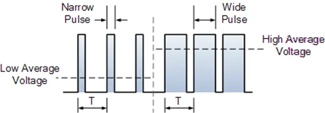
Figure 7: PWM from electronics-tutorial.ws
As we can clearly see from the pulse generator block, the pulse width is 75% by default which means voltage source is ON for 75% of time for one cycle and 25% of time motor receives no voltage. We can modify the pulse-width or duty cycle to prevent the motor current from shooting up while changing direction from forward to reverse.
Thus by varying the pulse-width, we can vary the average voltage across a DC motor and hence its speed can be altered as well.
Figure 8: Pulse generator block with default parameters
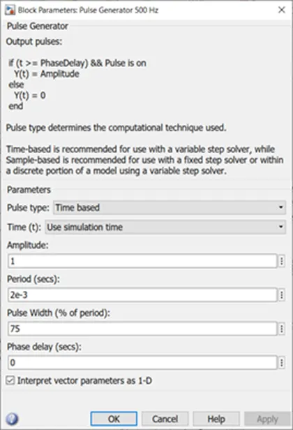
By changing the pulse-width i.e. duty cycle to 40% we obtain the following graphs.
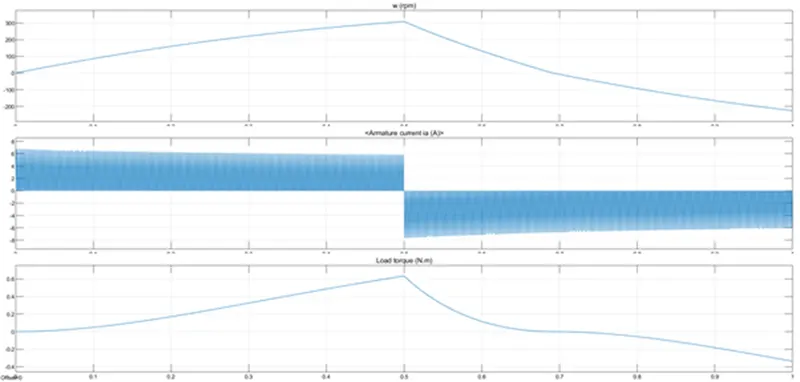
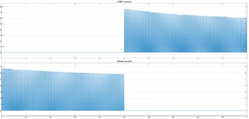
Figure 9: Image showing graphs when duty cycle is reduced to 40%
From these graphs it is clearly visible that armature current doesn’t shoot up in the positive direction attains maximum at about +7 amps and also in the negative direction it attains a maximum peak value of about -7 amps.
Class E chopper-
A four quadrant chopper or Class E chopper is a chopper which can operate in all the four quadrants. The power can flow either from source to load or load to source in this chopper.
In MatLab to open the model for this chopper type “dc7_example”.
The Four quadrant chopper DC Drive (DC7) block represents a four-quadrant, DC-supplied chopper drive for DC motors. This drive features closed-loop speed control with four-quadrant operation. The speed control loop outputs the reference armature current of the machine. Using a PI current controller, the chopper duty cycle corresponding to the commanded armature current is derived. This duty cycle is then compared with a saw-tooth carrier signal to obtain the required PWM signals for the chopper.
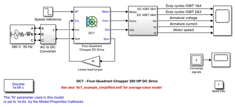
Figure 10: Four quadrant chopper drive
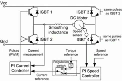
Figure 11: Circuit diagram for DC7
Comparison between Class E chopper and H-bridge-
|
S.No. |
Class E Chopper |
H-Bridge |
|
1 |
Regenerative braking is possible. |
Dynamic braking can be achieved only. |
|
2 |
Lesser power dissipation |
Significantly more power losses are observed. |
|
3 |
Less maintenance is required due to smooth acceleration and deceleration. |
Risk of damage to the motor is more due to sudden current spikes. |
|
4 |
They are commonly employed in automobiles. |
They are commonly employed in robotics and electro-mechanical devices. |
|
5 |
The current values are chopped thus simulation time is less. |
The current values are continuous thus simulation takes time. |
|
6 |
Direction can be reversed by interrupting one signal to another. |
Direction can be reversed just by changing the polarity of the circuit. |
|
7 |
It has a better efficiency. |
Its efficiency is comparatively less. |
EV model using DC7 block-
This model for an Electric Vehicle is made by using the four quadrant chopper drive.
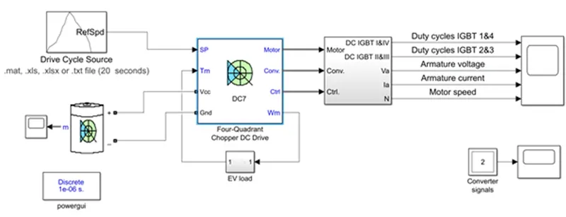
Figure 12: EV model using Class E chopper
Here, a custom drive cycle is given for reference, the battery is modelled by using battery block & specifications BMW i3s is taken.
For this EV model the motor speed-torque characteristics used is given as-
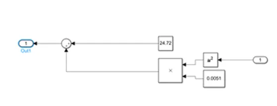
Figure 13: Speed-torque characteristics modelled in Simulink
Results-
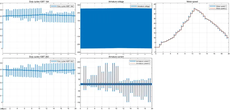
From the results obtained we can see the duty cycle of IGBT switches 1&4 suddenly rose in order to provide the required voltage to the motor. Throughout the whole drive cycle the duty cycle continues to operate in pulses to provide required voltage to EV. The duty cycle is maximum (0.6) at 10 sec where maximum motor angular speed is observed (40 rad/sec).
Whenever the motor’s angular speed increases the duty cycle also increases so that the average voltage is also increased.
The armature voltage block seems to be fluctuating between -250 and 260 V at a relatively high frequency. The armature voltage is fluctuating because of power switching occurring between IGBTs.
The armature current shows a spike initially when the motors starts and then it stabilizes after 0.1 sec. Here also the fluctuations occur rapidly due to switching of IGBTs.
Motor speed increases from 0 to 40 rad/sec at 10 sec then decreases to 0 at 20 sec. This plot is just drive cycle data.
BLDC Motor working-
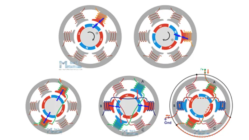
BLDC motor works on the principle of Lorentz force law which states that whenever a current carrying conductor placed in a magnetic field it experiences a force. As a consequence of reaction force, the magnet will experience an equal and opposite force. In the BLDC motor, the current carrying conductor is stationary and the permanent magnet is moving.
When the stator coils get a supply from source, it becomes electromagnet and starts producing the uniform field in the air gap. Though the source of supply is DC, switching makes to generate an AC voltage waveform with trapezoidal shape. Due to interaction between electromagnet stator and permanent magnet rotor, the rotor continues to rotate.
With the switching of windings as High and Low signals, corresponding winding energized as North and South poles. The permanent magnet rotor with North and South poles align with stator poles which causes the motor to rotate.
Conclusion - By above answer we see that how the hBridge for DC motor works and also the role of the BLDC motor in it. we simulate the model using dc7 block to see the result.
Thanking you.