Week-7 Challenge: DC Motor Control
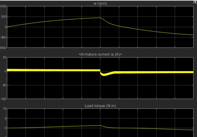
1. Run MATLAB demo ‘Speed control of a DC motor using BJT H-bridge’. Modify the model such that armature current doesn’t shoot up when motor changes direction from forward to reverse.
Speed Control of a DC Motor Using BJT H-Bridge
This example shows the simulation of an H-bridge used to generate a chopped voltage and to control the speed of a DC motor.
Description
The Bipolar Junction Transistor (BJT) when used for power switching applications, operates as an IGBT. When it is conducting (BJT operating in the saturated region), a forward voltage Vf is developed between collector and emitter (in the range of 1 V). Therefore, the IGBT block can be used to model the BJT device.
The IGBT block does not simulate the gate current controlling the BJT or IGBT. The switch is controlled by a Simulink® signal (1/0). The DC motor uses the preset model (5 HP 24V 1750 rpm). It simulates a fan type load (where Load torque is proportional to square of speed). The armature mean voltage can be varied from 0 to 240 V when the duty cycle (specified in the Pulse Generator block) is varied from 0 to 100%.
The H-bridge consists of four BJT/Diode pairs (BJT simulated by IGBT models). Two transistors are switched simultaneously: Q1 and Q4 or Q2 and Q3. When Q1 and Q4 are fired, a positive voltage is applied to the motor and diodes D2-D3 operate as free-wheeling diodes when Q1 and Q4 are switched off. When Q2 and Q3 are fired, a negative voltage is applied to the motor and diodes D1-D4 operate as free-wheeling diodes when Q2 and Q3 are switched off.
Simulation
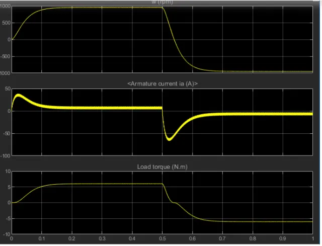
The motor starts in the positive direction with a duty cycle of 75% (mean DC voltage of 180V). At t= 0.5 sec., the armature voltage is suddenly reversed and the motor runs in the negative direction.
'Scope' shows motor speed, armature current and load torque and 'Currents' shows currents flowing in BJT Q3 and diode D3.
2. Refer to help section of ‘The Four-Quadrant Chopper DC Drive (DC7) block’. Compare it with H-bridge model.
The Four-Quadrant Chopper DC Drive (DC7) block represents a four-quadrant, DC-supplied, chopper (or DC-DC PWM converter) drive for DC motors. This drive features closed-loop speed control with four-quadrant operation. The speed control loop outputs the reference armature current of the machine. Using a PI current controller, the chopper duty cycle corresponding to the commanded armature current is derived. This duty cycle is then compared with a sawtooth carrier signal to obtain the required PWM signals for the chopper.
The main advantage of this drive, compared with other DC drives, is that it can operate in all four quadrants (forward motoring, reverse regeneration, reverse motoring, and forward regeneration). In addition, due to the use of high switching frequency DC-DC converters, a lower armature current ripple (compared with thyristor-based DC drives) is obtained. However, four switching devices are required, which increases the complexity of the drive system.
Note
In Simscape™ Electrical™ Specialized Power Systems oftware, the Four-Quadrant Chopper DC Drive block is commonly called the DC7 motor drive.
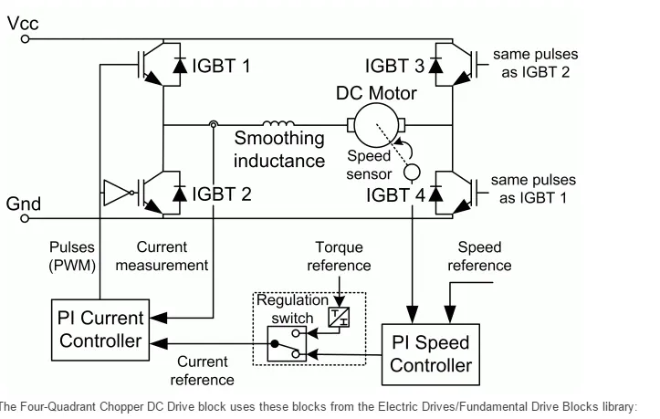
The Four-Quadrant Chopper DC Drive block uses these blocks from the Electric Drives/Fundamental Drive Blocks library:
Speed Controller (DC)
Regulation Switch
Current Controller (DC)
Chopper
3.Make a suitable EV model using DC7 block and make result report.
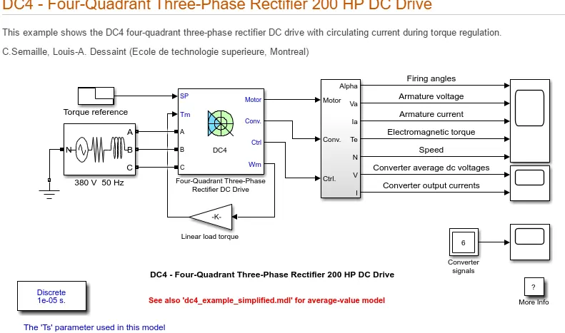
This example shows the DC4 four-quadrant three-phase rectifier DC drive with circulating current during torque regulation.
Description
This circuit uses the DC4 block of Specialized Power Systems. It models a four-quadrant three-phase rectifier (dual-converter topology) drive for a 200 HP DC motor.
The 200 HP DC motor is separately excited with a constant 310 V DC field voltage source. The armature voltage is provided by two three-phase anti-parallel connected converters controlled by two PI regulators. This allows bidirectional current flow through the DC motor armature circuit and thus four-quadrant operation. The converters are fed by a 380 V AC 50 Hz voltage source.
The regulators control the firing angles of both converter thyristors. The first regulator is a speed regulator, followed by a current regulator. Since we are here in torque regulation mode, the speed regulator is disabled and only the current regulator is used. The current regulator controls the armature current by computing the appropriate thyristor firing angles. This generates the rectifier output voltages needed to obtain the desired armature current and thus the desired electromagnetic torque.
Both converters operate simultaneously and the two firing angles are controlled so that their sum gives 180 degrees. This produces opposite average voltages at the converter dc output terminals and thus identical average voltages at the DC motor armature, the converters being connected in anti-parallel. One converter is working in rectifier mode while the other is in inverter mode.
The circulating current produced by the instantaneous voltage difference at the terminal of both converters is limited by 5 mH inductors connected between these terminals. No smoothing inductance is placed in series with the armature circuit, the armature current oscillations being quite small due to the three-phase voltage source.
Simulation
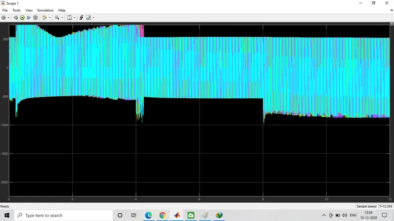
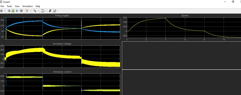
Start the simulation. You can observe the motor armature voltage and current, the converter firing angles, the electromagnetic torque and the motor speed on the scope. The current and torque references are also shown. A second scope allows you to visualize the converter average output voltages and output currents.
The motor is coupled to a linear load, which means that the mechanical torque of the load is proportional to the speed.
The initial torque reference is set to 0 N.m and the armature current is null. No electromagnetic torque is produced and the motor stays still.
At t = 0.2 s, the torque reference jumps to 600 N.m. This causes the armature current to rise to about 180 A. The armature current is supplied by converter 1, and the total current in this converter is the sum of load current and circulating current. Converter 2 simply carries the circulating current. Notice that the armature current follows the reference current quite accurately, with fast response time and small overshooting. Observe also that the firing angles are symmetrical around 90 degrees and that the converter average output DC voltages are equal but of opposite signs.
The electromagnetic torque produced by the armature current flow causes the motor to accelerate. The speed rises and starts to stabilize around t = 4 s at about 560 rpm, the sum of the load and viscous friction torques beginning to equalize the electromagnetic torque.
At t = 4 s, the torque reference is set to 0 N.m and the load torque causes the motor to decelerate. Notice that the four reactors keep the current oscillations quite small.
At t = 8 s, the torque reference is set to -300 N.m. The armature current jumps down to -90 A and is now delivered by converter 2 while converter 1 only handles the circulating current. Converter 2 is now working in rectifier mode and converter 1 in inverter mode.
The negative electromagnetic torque produced allows the motor to accelerate in the negative speed plane.
At t = 12 s, speed starts to stabilize around -290 rpm.
Notes
1) The power system has been discretized with a 10 us time step. The control system (regulators) uses a 100 us sample time in order to simulate a microcontroller control device.
2) In order to reduce the number of points stored in the scope memory, a decimation factor of 20 is used.
3) A simplified version of the model using average-value rectifiers can be used by selecting 'Average' in the 'Model detail level' menu of the graphical user-interface. The time step can then be increased up to the control system sample time value.This can be done by typing 'Ts = 100e-6' in the workspace in the case of this example. See also dc4_example_simplified example.