Week-7 Challenge: DC Motor Control
- AIM
- 1) Run MATLAB demo ‘Speed control of a DC motor using BJT H-bridge’. Modify the model such that armature current doesn’t shoot up when motor changes direction from forward to reverse.
- 2) Refer to help section of ‘The Four-Quadrant Chopper DC Drive (DC7) block’. Compare it with H-bridge model.
- 3) Make a suitable EV model using DC7 block and make result report.
- OBJECTIVE
- 1) Reduce the duty cycle in such a way that the shooting up of armature current during reverse
- 2) To learn about Four-Quadrant Chopper DC Drive (DC7) block and infer how it is different from a BJT H-bridge used for speed control
- 3)
- METHOD
- 1) An H bridge is used to control the speed. An H-Bridge is made up of four switches: two in series, and two in parallel, with the load placed in between the switches.
-

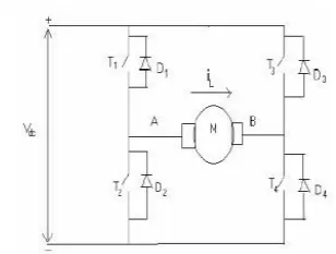
- H bridge works by applying voltages across load in either direction. To initiate a change direction of the voltage supplied, the H-Bridge controls the switches that deliver power to the load (
S1). In the above diagram ifS1is closes andS4while leaving the rest open, the voltage will be applied from left to right across the motor. IfS2andS3are closed instead and the others open, the voltage will be applied from right to left. - The required model is opened from matlab documentation.
-
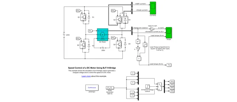
- The H-bridge consists of four BJT/Diode pairs (BJT simulated by IGBT models). Two transistors are switched simultaneously: Q1 and Q4 or Q2 and Q3. When Q1 and Q4 are fired, a positive voltage is applied to the motor and diodes D2-D3 operate as free-wheeling diodes when Q1 and Q4 are switched off. When Q2 and Q3 are fired, a negative voltage is applied to the motor and diodes D1-D4 operate as free-wheeling diodes when Q2 and Q3 are switched off.The H-bridge consists of four BJT/Diode pairs (BJT simulated by IGBT models). Two transistors are switched simultaneously: Q1 and Q4 or Q2 and Q3. When Q1 and Q4 are fired, a positive voltage is applied to the motor and diodes D2-D3 operate as free-wheeling diodes when Q1 and Q4 are switched off. When Q2 and Q3 are fired, a negative voltage is applied to the motor and diodes D1-D4 operate as free-wheeling diodes when Q2 and Q3 are switched off. The duty cycle can be changed to reduce the peak of current during reverse operation.
- 2) Understand the difference between H bridge and Four quadrant chopper. The operations of a H bridge can be seen as first and third quadrant operation of a four-quadrant chopper operation
- 3) A drive cycle data is made as below:
-

- The total drive cycle is simulated for a time of 59.6 sec with a time step of 0.1 sec
- A DC battery source is selected and its default parameters are used.
- A current measurement block is attached to the DC battery source.
- Using Ws as input a Torque equation is modeled and made into a subsystem block:
-
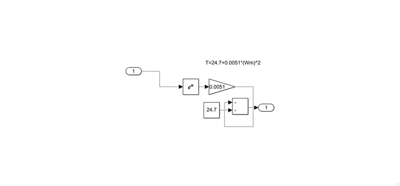
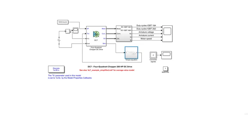
- The model is decipted below:
-
- RESULTS
- 1) Duty cycle is the ratio of time a load or circuit is ON compared to the time the load or circuit is OFF. Initially the simulation is run with a 75% duty cycle.
- The zero cross over detection is enabled in model setting to avoid error due to discontinuity and the above result is obtained with default value. Then the duty cycle % is changed to 45%. The model parameters for pulse generator block is defined below:
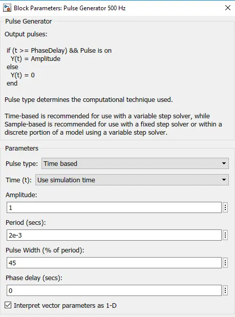
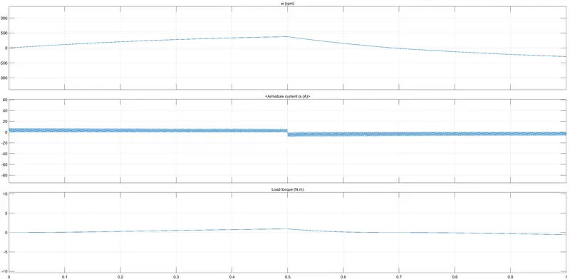
- The sharp peak in current is overcome at a value of 45% for duty cycle due to reversing.
- 2) Both H bridge circuits and four-quadrant chopper are used for speed control. The H bridge operation only facilitates functioning similar to first and third quadrant of a four-quadrant chopper.
-
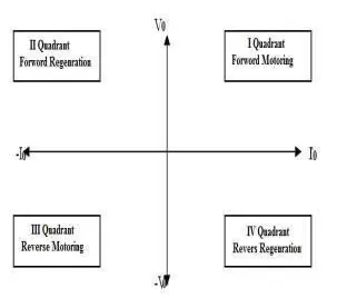
- Four Quadrant DC motors are extremely used in adjustable speed drive and position control applications. Their speeds below the base speed can be controlled by armature-voltage control. Speeds above the base speed are obtained . The main advantage of this drive, compared with other DC drives, is that it can operate in all four quadrants (forward motoring, reverse regeneration, reverse motoring, and forward regeneration). In addition, due to the use of high switching frequency DC-DC converters.
- In the first quadrant, both current and voltage are positive in nature and facilitates motor rotation in the forward direction and is called forward motoring. The change in polarity of both and their different combination facilitates its four-quadrant operation.
- a) First Quadrant:-When the supply is given to the circuit the T1 and T4 is ON, the current flowing through the path,(Vdc+) -T1 –
Load (A-B) -T4 –(Vdc-). Hence both current and voltage are positive. During this condition, the inductance gets charged by positive polarity. The first quadrant operation can be achieved called as forward motoring
b) Second Quadrant:-During third quadrant operation inductor get fully charge it find a path to get discharge during discharge
the energy can be dissipated through Load(B) –D1 –(Vdc+) –(Vdc-) –D4 –Load(A) since the voltage is positive and current is negative and second quadrant operation can be achieved. This is called as forward regeneration.
c) Third Quadrant;-When T2 and T3 are turned-on current start to flow through path (Vdc+) –T3 –Load (B-A) –T2 –(Vdc-),the current and voltage are negative. the second quadrant operation can be achieved.The inductor get charged again with the same polarity.
d) Fourth Quadrant:-During first quadrant operation inductor get fully changed it will find the path to discharge for that. This is called as reverse motoring.
inductor change the polarity and get discharged through path Load(B) -D3 –( Vdc+) –(Vdc -) –D2 –Load(A) in that case voltage negative and current is positive the fourth quadrant operation can be achieved.This is called as reverse regeneration. - 3)
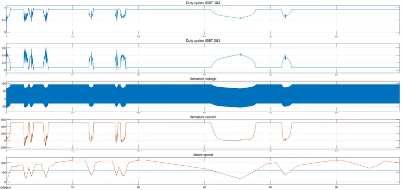
- From the onset, it is clear that when the signal across the IGBT 1 and 4 is high, the signal across IGBT 2 and 3 is low. As the signal across that increases, the signal across IGBT 1 and 4 gradually decreases. With the increase in motor speed, the current requirement increases. When the motor speed goes down, so does the current requirement. This lead to a sharp decline in the Armature current. During the braking, there is regenerative braking. This leads to the negative armature current. The operating voltage resonates with the duty cycle and operation of the motor.
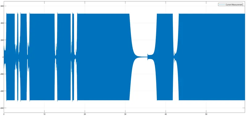
- It can be seen that as there is an increase in current drawn from battery there is corresponding increase in torque as well.