DC Motor Control
- Aim
To simulate and study about DC drive of electric vehicle (EV)
Objectives
- To run MATLAB demo ‘Speed control of a DC motor using BJT H-bridge’. Modify this model armature current doesn’t shoot up when motor changes direction from forward to reverse.
- To simulate the model ‘The four quadrant chopper DC drive (DC7) block’ and to compare it with H-bridge model.
- To make a suitable EV model using DC7 block and make result report.
Simulations
1.BJT H-bridge
Permanent magnet AC machines with trapezoidal back emf wave forms are known as the PM brushless DC machines. The concentrated windings of the machine instead of sinusoidal distributed windings on the stator are the reason for trapezoidal shaped back emf wave forms. In case of DC motors, it can be easily controlled. Equation and graph represented below shows that.
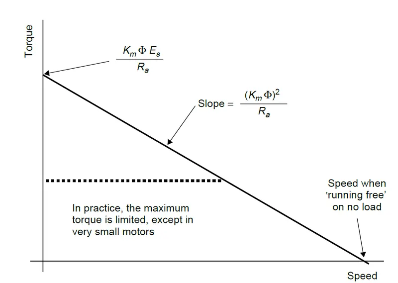
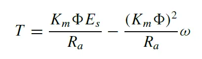
If the supply voltage is reduced, then maximum torque falls in proportion and the slope of the graph is unchanged. Any torque and speed can be achieved below maximum values. Changing magnetic flux is also a way to control the DC motor speed. Speed control of a DC motor using BJT H-bridge shows the simulation of an H bridge used to generate a chopped voltage and to control the speed of a DC motor. We can load this model using help button in mat lab and the model is represented below.
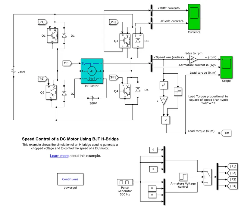
The Bipolar Junction Transistor (BJT) when used for power switching applications operates as an IGBT. When it is conducting (BJT operating in the saturated region), a forward voltage Vf is developed between collector and emitter (in the range of 1V). The IGBT block can be used to model the BJT device. The IGBT block does not simulate the gate current controlling the BJT or IGBT. The DC motor uses the present model (5HP 24V 1750rpm). It simulates a fan type load, where load torque is proportional to square of speed. The armature means voltage can be varied from 0 to 240V when the duty cycle which is specified in pulse generator block is varied from 0 to 100%. The H Bridge consists of four BJT/Diode pairs. Two transistors are switched simultaneously. When Q1 and Q4 are fired, a positive voltage is applied to the monitor diodes D2-D3 operates as freewheeling diodes when Q1 and Q4 are switched off. When Q2 and Q3 are fired, a negative voltage is applied to the motor and diodes D1-D4 operates as freewheeling diodes hen Q2 and Q3 are switched off. The motor starts in the positive direction with a duty cycle of 75% (mean DC voltage of 180V). At t = 0.5 sec, the armature voltage is suddenly reverse and the motor runs in the negative direction. The scope block shows motor speed, armature current and load toque and currents block shows currents flowing in BJT Q3 and diode D3.
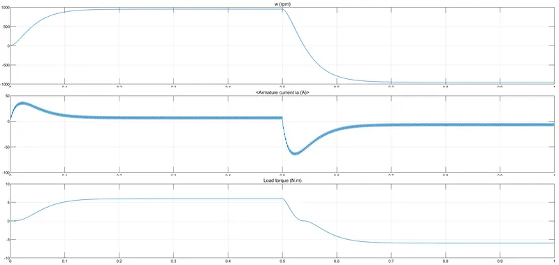
In the result, the armature current shoots up when motor changes direction. It can be noticed when time is 0.5 seconds. Now we want to modify this model so that armature current doesn’t shoot up when motor changes direction from forward to reverse. Consider the pulse generator block in the model and it is represented below.
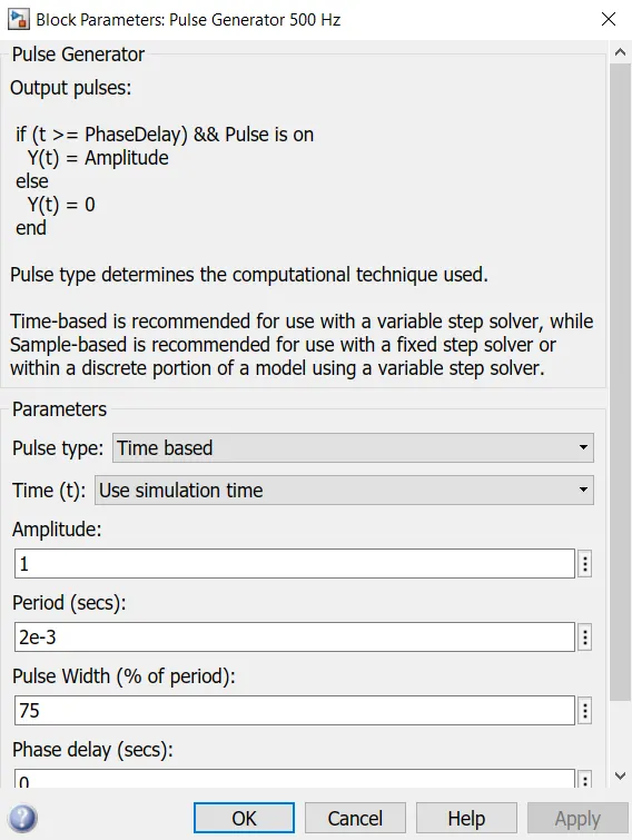
Here, the pulse width is 75%. Now let’s change it to 50% and run the simulation. The result is given below.
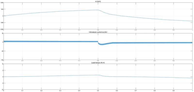
From the result, we can notice that the current change was not that severe when compared to previous case. Now run the simulation with 35% pulse width.
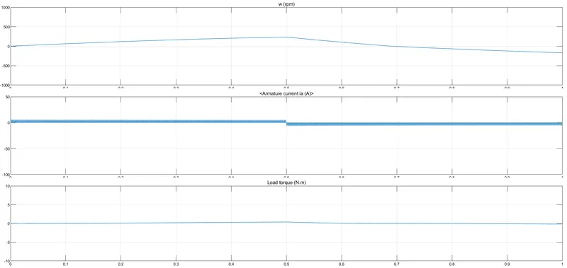
The result shows very less change in armature current. Load torque and rpm is almost constant.
2. Four quadrant chopper DC drive
Now we want to simulate the model ‘The four quadrant chopper DC drive (DC7) block’ and to compare it with H-bridge model which was represented above. DC7 block is also loaded from the help button and it is represented below.
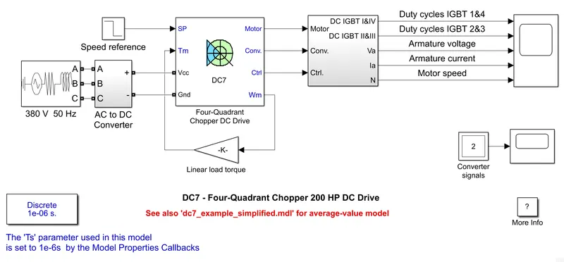
In this model, 200HP DC motor is separately excited with a constant 150V DC field voltage source. Armature voltage is from IGBT converter and it is fed with 515V DC. Braking chopper limits the DC bus voltage during dynamic mode. All the other description of the model and simulation conditions is given in the mat lab documentation itself. Result of the simulation is represented below.
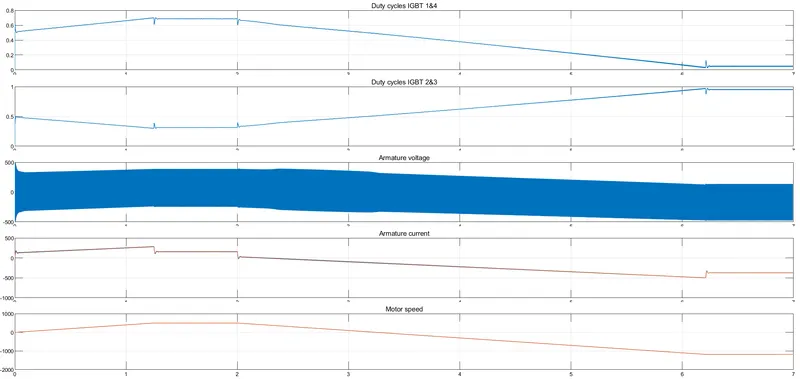
When we compare the result with the previous model it is clear that, there is no sudden change in armature current and the efficiency of the model is high. But the simulation time is more than other model. Its working in all four quadrants is also an advantage.
3. EV model using DC7 block
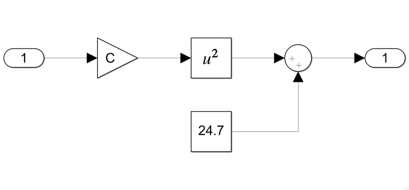
Here, we are trying to make a suitable EV model using DC7 block. For that, a DC source battery and a current sensor which is series to that is placed for AC to DC converter and rectifier in existing model of DC7 block. AC source is also replaced with a DC battery to simulate the electric vehicle. We must also consider the torque speed equation and must provide a drive cycle externally. These changes were made in the model and the model is given below.
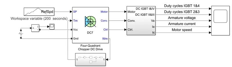
In this model the torque speed relation is added as a sub system and it is given below.
epesentation of drive cycle is also given below
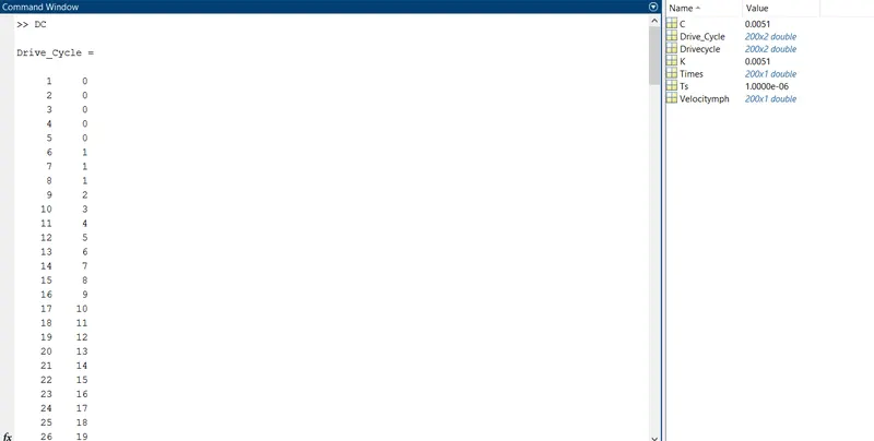
After setting the simulation time to 200 seconds according to the external drive cycle, simulation is carried out and result is given below
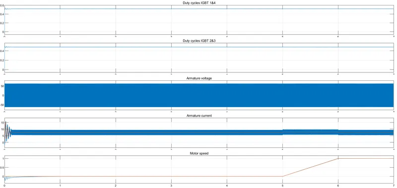
We can observe a steady electric vehicle motor from the result.
Conclusion
Simulations were done and results were obtained.
Reference
[2] Electric Vehicle Technology Explained, James Larminie and John Lowry, John Wiley & Sons Ltd
[3] ELECTRIC and HYBRID VEHICLES Design Fundamentals, Iqbal Husain, 2003, CRC Press LLC