Week-7 Challenge: DC Motor Control
Ans 1)
Command window input: power_Hbridge
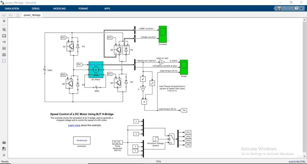
This model is used to generate a chopped voltage and to control the speed of a DC motor using BJT H-bridge.
BJT: They have 3 terminals: emitter , base and collector.The current flows through emitter and collector and the amount of current that flows through them is controlled by the base.
BJT is classified into two types :
1) PNP transistor: The emitter terminal is more positive than collector and base terminals. When the base voltage is same as emitter voltage, the transistor is in OFF state and when the base voltage decreases with respect to the emitter voltage, the transistor is in ON state.
NPN Transistor: The p-type semi-conductor will be the the base of the transistor. When the base voltage is same as emitter voltage then the transistor is in OFF state whereas when base voltage increases w.r.t. to emitter voltage, the transistor is in ON state.
BJT H-Bridge:
When the BJT is conducting i.e. operating in the saturated region, there will be a forward voltage developed between the collector and emitter terminals. The duty cycle can be changed from pulse generator block.
The H-Bridge consists of 4 BJT and diode pairs.When Q1 and Q4 are fired, a positive voltage is supplied to the motor and the diodes, D2 and D3 operates as free wheeling diodes similarly when Q2 and Q3 are fired, a negative voltage is applied to the motor and diodes D1 and D4 operates as a free wheeling diodes.
The pulse generator block is having preset value for pulse width field as 75%
When run with default set of values we get the following image as the output:
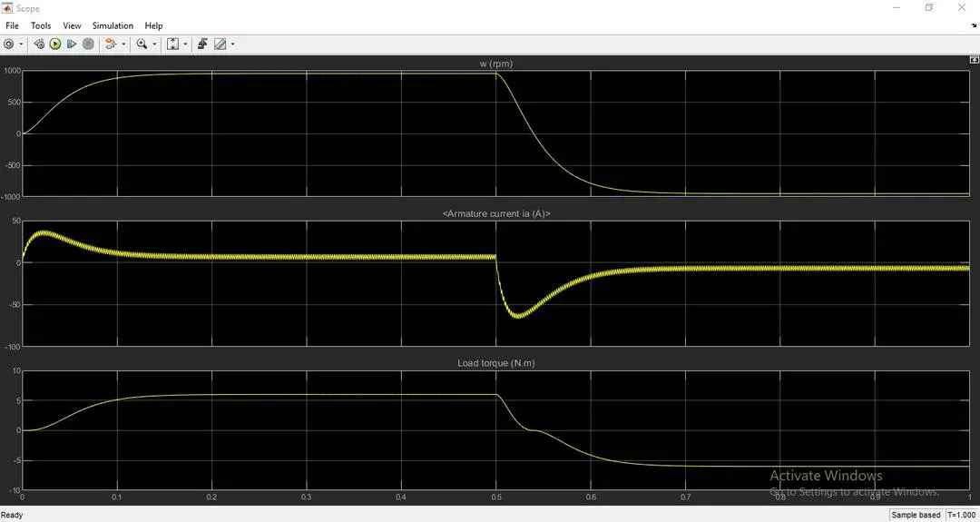
The current shoots up initially and also in the negative direction when it changes direction.
If we change the duty cycle i.e. the pulse width, we can neutralize the initial shoot up of the current.
The output after reducing the pulse width from 75 % to 40 % is below:
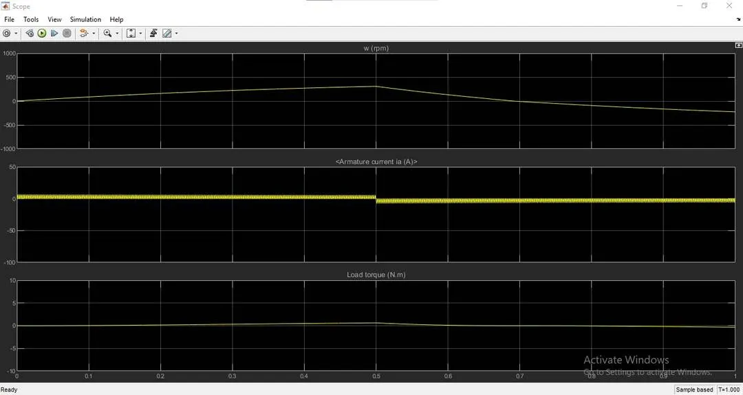
The current does not shoot up as we reduced the duty cycle to 40%.
Ans 2)
Command window input to open Four-Quadrant Chopper DC drive:
dc7_example
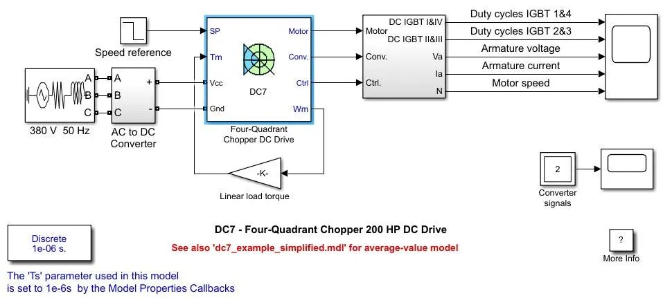
A 4 Quadrant DC chopper controls speed in all four quadrants of motor drive.It allows the controller to command the DC motor to rotate in clock or anti-clockwise directions and to perform braking.
The mode of operations that each quadrant exibits are:
QI - forward motoring
QII- reverse braking
Q3- reverse motoring
Q4- forward braking
The 4 Quadrant chopper DC drive uses these 4 main blocks from drive block library:
1) speed controller
2) current controller
3) regulation switch
4) chopper
Principle of operation:
Forward motoring: motor rotates clockwise and controller applies clockwise drive.
Reverse motoring: motor rotates anti-clockwise and controller applies an anti-clockwise drive.
Forward braking: motor rotates clockwiseband controller applies anti-clockwise drive.
Reverse braking: motor rotates anti-clockwise and controller applies clockwise drive.
Advantages:
4 quadrant choppers have more control over deceleration of the motor and can more accurately brake the motor.
It reduces the risk of current spikes which can occur when motor is made to brake while running at a high speed.
They are more efficient because lesser energy is wasted as heat and lesser current spikes takes place which inturn mean lesser power dissipation.
The 4 quadrant chopper makes regenerative braking possible, the kinetic energy of the rotor moving is transferred back as electrical energy which is used to charge the battery.
Comparison to H-Bridge:
4 quadrant chopper are used in electric vehicles whereas BJT H-Bridges are used in robotics and other electro-mechanical devices.
BJT H-Bridges are not capable of performing regenerative braking but can perform dynamic braking.
In DC chopper drive, the current signals are interrupted with one another to change the direction of motor. Speed reference or a drive cycle converts speed values to current signals. However in BJT H-Bridges, the polarity of the current is reversed to change the direction of rotation of the motor.
Current in DC choppers are not continuous (discrete) and so less time is taken for simulation. Though in BJT H-Bridges, the current values are continuous that is why they take more time for simulation.
A PI controller is used in DC chopper drives.
Ans 3)
Using the Four Quadrant DC chopper drive we are going to model an EV:
The Torque Equation:
T(m) = 0.0051w^2 + 24.7
w = angular speed of the motor
T(m) = Torque of the motor(Nm)
is added in the chopper load input and a drive cycle data is replaced with the speed reference block.
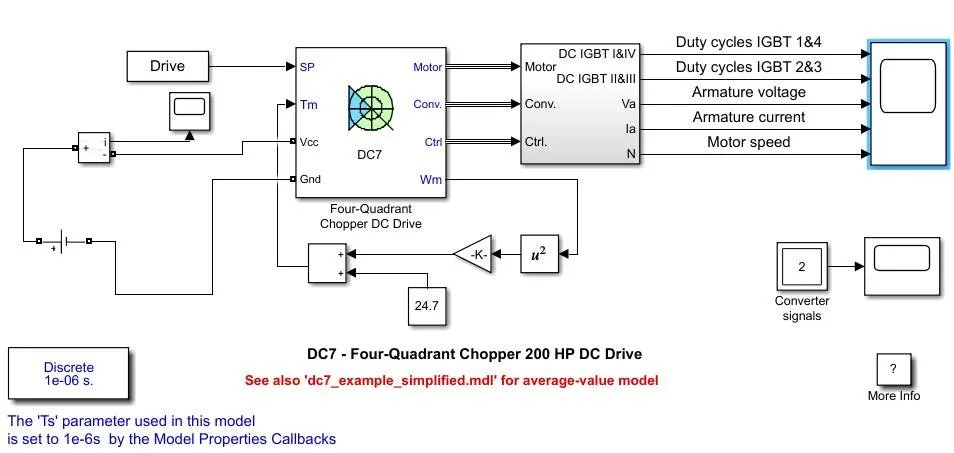
The blocks used to make the equations are:
1) Gain
2) Add
3) Constant
The AC voltage source is replaced with a DC voltage source of 200V.
A current measurement block is added to that DC voltage source. The i terminal of the current measurent block is connected to a 'scope' block.
The Drive cycle block is having the velocity data for 15 seconds.
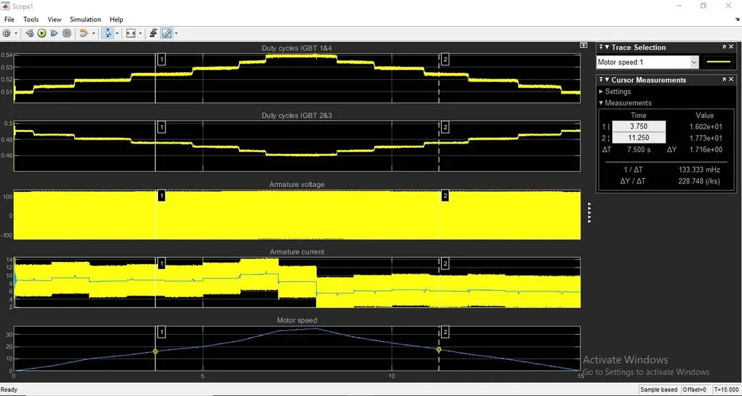
IGBT 1&4 Duty Cycle:
The spike in the starting is to adust the voltage at which the motor needs to operate. The duty cycle is seen in pulses if zoomed in on x-axis. The duty cycle increases to 0.54 at t = 7 seconds which is when the motor angular speed is maximum. When the motor angular speed increases the duty cycle also increases so that the average voltage supplied is more similarly motor angluar speed causes decrease in duty cycle which in turn causes average voltage to reduce.
IGBT 2&3 Duty Cycle:
Similar to IGBT 1&4 there is a spike in voltage to prive operating voltage.The duty cycle of IGBT switches 2 & 3 decreases in pulse as the motor angular speed increases.It reaches its minimum at 0.54 at seconds.
Armature Voltage:
The armature voltage fluctuates between 100 V and -100 V at a high frequency due to power switch between IGBT 1&4 and IGBT 2&3. When IGBT 1&4 are ON and switches 2&3 are off, the polarit of the armature voltage is positive. When IGBT 2&3 are ON and switches 1&4 are off the polarity of the armature voltage is negative
Armature Current:
After the initial spike the current stabilizes its fluctuations between 13 A to 3 A. The fluctuation limits decreases as the angular speed is decreased after 7 seconds.
The last plot is simply of motor speed we gave to the DC block.