Week-7 Challenge: DC Motor Control
1. A. Explain a MATLAB demo model named ‘Speed control of a DC motor using BJT H-bridge’.
B. Comment on the armature current shoot-up from the scope results.
C. Refer to the help section of ‘The Four-Quadrant Chopper DC Drive (DC7) block’. Compare it with the H-bridge model.
Aim:
- Run MATLAB demo ‘Speed control of a DC motor using BJT H-bride .Modify the model such that armature current doesn’t shoot up when motor changes direction from forward to reverse.
- Refer to help section of ‘The Four-Quadrant Chopper DC Drive (DC7) block’. Compare it with H-bridge model.
- Make a suitable EV model using DC7 block and make result report.
Speed control of a DC motor using BJT H-bridge
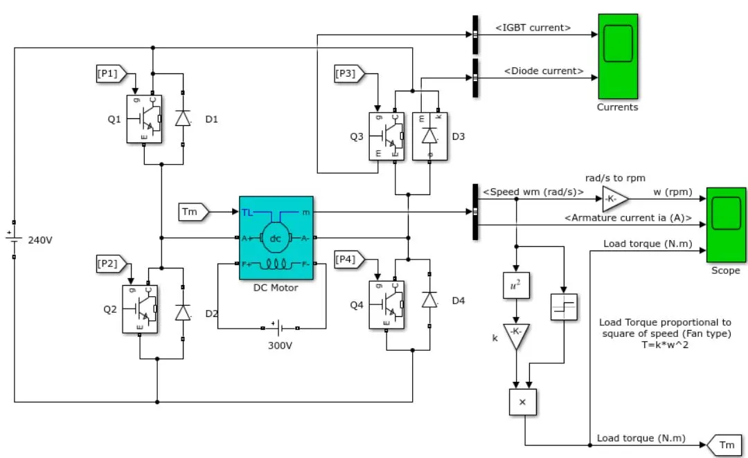
This example shows the simulation of an H-bridge used to generate a chopped voltage and to control the speed of a DC motor.
Description
H Bridge is a simple electronic circuit which enables us to apply voltage to load in either direction. It is commonly used in robotics application to control DC Motors. By using H Bridge we can run DC Motor in clockwise or anticlockwise directions. This circuit is also used to produce alternating waveforms in inverters.
The Bipolar Junction Transistor (BJT) when used for power switching applications, operates as an IGBT. When it is conducting (BJT operating in the saturated region), a forward voltage Vf is developed between collector and emitter (in the range of 1 V). Therefore, the IGBT block can be used to model the BJT device.
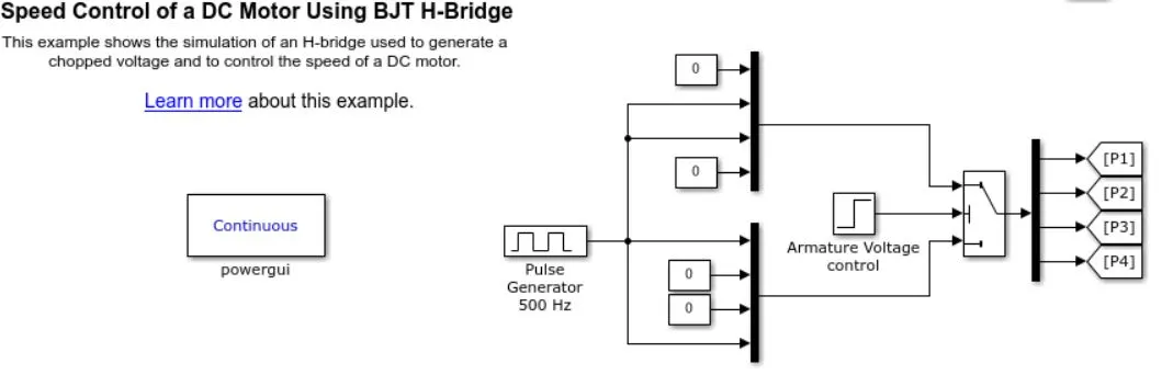
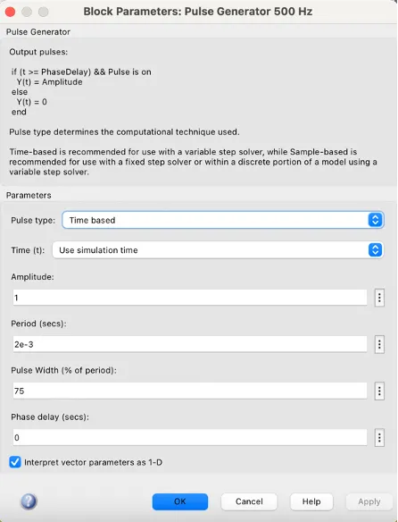
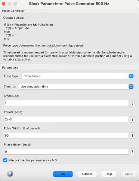
The IGBT block does not simulate the gate current controlling BJT or IGBT. The switch is controlled by a Simulink signal (1/0). The DC motor uses the preset model (5 HP 24V 1750 rpm). It simulates a fan type load (where Load torque is proportional to square of speed). The armature mean voltage can be varied from 0 to 240 V when the duty cycle (specified in the Pulse Generator block) is varied from 0 to 100%.
The H-bridge consists of four BJT/Diode pairs (BJT simulated by IGBT models). Two transistors are switched simultaneously: Q1 and Q4 or Q2 and Q3. When Q1 and Q4 are fired, a positive voltage is applied to the motor and diodes D2-D3 operate as free-wheeling diodes when Q1 and Q4 are switched off. When Q2 and Q3 are fired, a negative voltage is applied to the motor and diodes D1-D4 operate as free-wheeling diodes when Q2 and Q3 are switched off.
Simulation
The motor starts in the positive direction with a duty cycle of 75% (mean DC voltage of 180V). At t= 0.5 sec., the armature voltage is suddenly reversed and the motor runs in the negative direction.
'Scope' shows motor speed, armature current and load torque and 'Currents' shows currents flowing in BJT Q3 and diode D3.
The block has two values as a display of the output. One is the current output for the IGBTand the diode current and the other is the scope for the values of the DC motor. The values of the DC motor include-
1. Speed (in RPM)
2. Armature Current (in AMPS)
3. Load Torque (in N-m)
The output values are as follows:-
1. IGBT Current
2. Diode Current
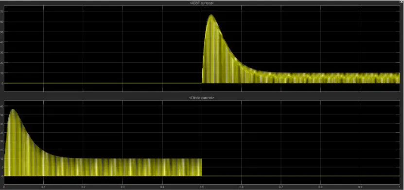
The values of the SCOPE are as follows-
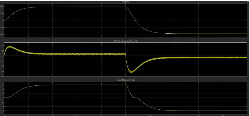
2. Develop a 2-quadrant chopper using Simulink & explain the working of the same with the relevant results.
Solution:
CIRCUIT DIAGRAM FOR TWO QUADRANT CHOPPER:
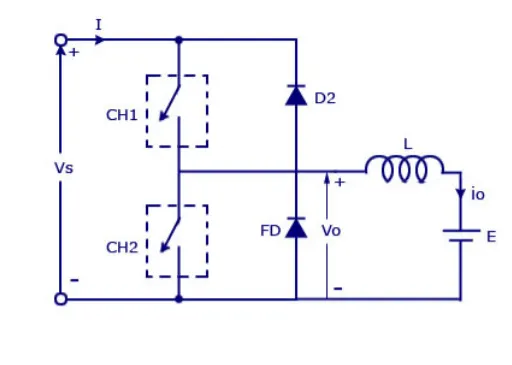
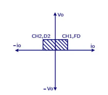
Two quadrant chopper is also called as type c chopper. Type C chopper is obtained by connecting type –A and type –B choppers in parallel. We will always get a positive output voltage V0 as the freewheeling diode FD is present across the load. When the chopper is on the freewheeling diode starts conducting and the output voltage v0 will be equal to Vs . The direction of the load current i0 will be reversed. The current i0 will be flowing towards the source and it will be positive regardless the chopper is on or the FD conducts. The load current will be negative if the chopper is or the diode D2 conducts. We can say the chopper and FD operate together as type-A chopper in first quadrant. In the second quadrant, the chopper and D2 will operate together as type –B chopper.
The average voltage will be always positive but the average load current might be positive or negative. The power flow may be life the first quadrant operation ie from source to load or from load to source like the second quadrant operation. The two choppers should not be turned on simultaneously as the combined action my cause a short circuit in supply lines. For regenerative braking and motoring these type of chopper configuration is used.
SIMULINK MODEL FOR TWO QUADRANT CHOPPER :
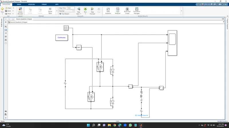
let us take two mosfet blocks and diodes blocks and connect it as shown in circuit diagram.
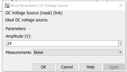
The dc voltage source is connected as shown.
let the voltage of dc voltage source be 24 volts.
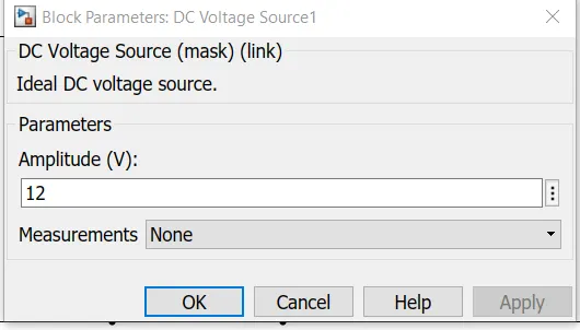
let us consider an series RLC branch block and select inductor L . thus block works as a load.
To consider LE load ie motor load , and dc voltage source of 12 volt is also connected in series with inductor.
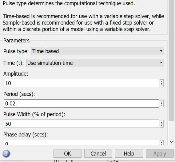
The pulse generator block is used to create gate pulse.
The not gate is used in the model so that the two mosfet will not get closed at the same time otherwise short circuit will occur .due to use of not gate , when one mosfet is ON the other mosfet will get off and when other mosfet is ON the first mosfet will get off .
The amplitude of pulse generator is kept 10 so that we can clearly see the pulses at scope and let period be 0.02 seconds and let pulse weidth be 50%
SCOPE RESULT:
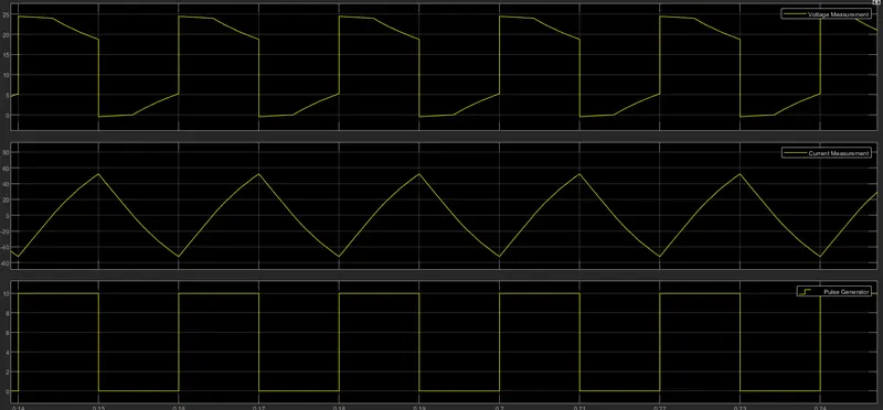
The pulse amplitude is 10 thus from pulse waveform we can see that the pulse amplitude is 10.
3. Explain in a brief, the operation of the BLDC motor.
BLDC- Brushless DC motor
DC motor which does not have brushes and controller provides current pulses to the motor winding which controls the torque and speed of the motor is BLDC.
In brushless motors, the problem of connecting current to the armature is overcome by permanent magnets rotating around a fixed armature. Over a vast speed range, these type of motors is very efficient in producing large amounts of torque.
Working principle:
There are only two basic parts in the BLDC motor they are stator and rotor. The stator is the resting part and contains windings the rotor is the rotating part and contains magnets. In BLDC permanent magnets are attached to the rotor and move the electromagnets to the stator.
To activate electromagnets for the shaft turns high power transistors are used. Using a solid-state circuit the controller performs power distribution
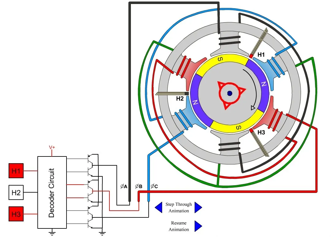
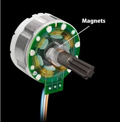
When the stator coils get a supply from the source, it becomes an electromagnet and starts producing the uniform field in the air gap. Though the source of supply is DC, switching makes to generates an AC voltage waveform with a trapezoidal shape. Due to the force of interaction between the electromagnet stator and permanent magnet rotor, the rotor continues to rotate.
With the switching of windings as High and Low signals, corresponding winding energized as North and South poles. The permanent magnet rotor with North and South poles aligns with stator poles which causes the motor to rotate.
In two-quadrant chopper drive both motoring mode and regenerative mode (two quadrant dc motor drive).
Types of BLDC
- Inner rotor design
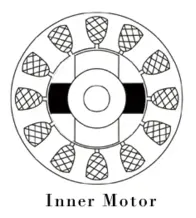
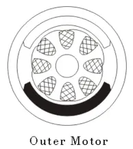
- Outer rotor design
Advantages of BLDC:
- More efficient because the velocity of BLDC is determined by the frequency at which the current is applied and does not depend on voltage.
- Mechanical energy losses because of friction are less due to the absence of brushes.
- Can operate at high speed under any condition.
- Less noise and no sparking under any condition
- For much precise control, more electromagnets can be used
Disadvantages of BLDC:
- Cost is higher compared to brushed dc motor
- Only limited power could be supplied to the motor because the high amount of heat weakens the magnets and insulation may get damaged.