Week-7 Challenge: DC Motor Control
1. A. Explain a MATLAB demo model named ‘Speed control of a DC motor using BJT H-bridge’.
B. Comment on the armature current shoot-up from the scope results.
C. Refer to the help section of ‘The Four-Quadrant Chopper DC Drive (DC7) block’. Compare it with the H-bridge model.
2. Develop a 2-quadrant chopper using simulink & explain the working of the same with the relevant results. (Refer to article - Multiquadrant operation of motor )
3. Explain in a brief about operation of BLDC motor.
1. A). Explain a MATLAB demo model named ‘Speed control of a DC motor using BJT H-bridge’.
Model
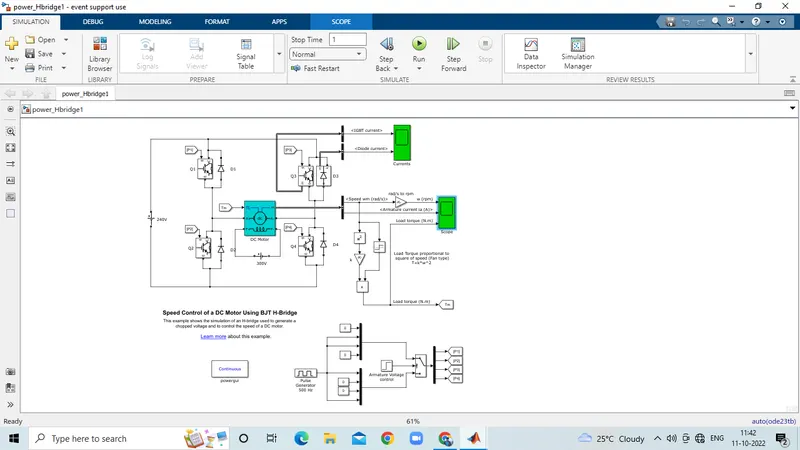
A)Working of H-bridge model:
- Here H-bridge DC chopper circuit is designed to control the speed of the motor.
- IGBT acts as BJT in power switching devices.
- Four IGBT switches are used for inverting the DC voltage 0 to 240 v supply.The current flows from collector(C) to emitter(E).
- The gate are controlled by the pulses(0 and 1) according to the armature voltge of motor given by pulse generator.
- This image shoes the voltage value given from initial to final during the step time.According to the pulses on and off the voltage supplied to the IGBT's.
- Here four switches are used Q1,Q2,Q3,Q4. Pulses P1,P2,P3,P4 are conected with corresponding switches.
- In first state, Q1 and Q4 are closed by giving 1V to IGBT'S,current from battery passes through Q1 and Q4.Diode D2,D3 are used as free wheeling diode in this state.In this case Forward motoring and forward breaking are held.
- In Second state,Q2 and Q3 are closed by giving 1V to IGBT's,current from battery passes through Q2 and Q3.Diode D1,D4 are used as free wheeling diode in this stateIn this case reverse motoring and reverse breaking are held.The current direction change its direction in this state.
- Both the states are occuring in 0.5 seconds in their sample time.Thus DC supply converted and feeded to the armature of the motor.
- Here free wheeling diodes are used as a safety purpose of this inverter circuit as when the flow of current on low values protects the circuit and machine by feed backing the current or in high voltage fluctuvations voltage get splited as protection to the motor and circuit components.
- In motor operation, armature terminals are connected with a 240V along the inverter circuit and field windings are connected with 300 V DC suppy to act as a electro magnet for the motor.
- The load torque is given as mechanical input to the motor for its referance.
- Thus through this magnetic fields generated, variable current carring conductors in rotor armature produces forces according to fleming left hand rule principle. Thus the motor starts to rotate.
- Here run this demo model and study the results from scopes.
Results
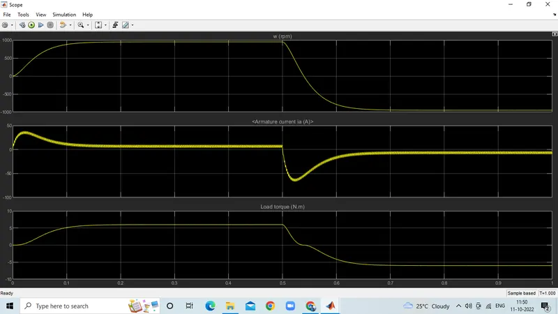
Speed of motor:
- Initially increases to 0 to nearly 900 rpm upto 0.5 secs(Forward motoring action takes place).
- Then speed reduces to 0 rpm(Forward dynamic breaking action takes place).
- Then speed increases from 0 to -900 rpm at upto 1 sec( Reverse motoring action takes place).
- Then reverse dynasmic breaking occurs(Not shown in scope).
Load torque of motor:
- Initially torque increase from 0 to 0.5 secs in forward motoring action.
- Then torque reduces to 0 Nm in forward dynamic breaking mode.
- Then torque increases in reverse direction in reverse motoring action upto 1 sec.
- Again torque reduce to zero.(Not shown in scope).
B). Comment on the armature current shoot-up from the scope results.
from armature current graph , we can see that ,at starting there is sudden spike increase in current at 0 sec also and at 0.5 sec also means at transition from positive to negative direction of rotation we observe a high surge in current, this is due to the transient switching occurring in the circuit.
As there is already current flowing in the circuit & on changing of switches after 0.5 sec, the current in the circuit adds to the changed direction of current and we observe a surge in current.
the surge in the current can be reduced by reducing the duty cycle.
in above results , the duty cycle selected as 75%.
by changing the duty cycle from 75% to 50% , the current surge can be reduced tremendously.
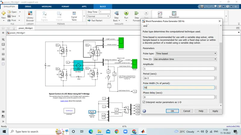
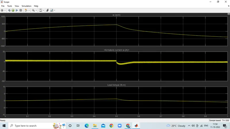
thus we can find that , the armature curent spike is reduced by changing the duty cycle from 75% to 50%.
C. Refer to the help section of ‘The Four-Quadrant Chopper DC Drive (DC7) block’. Compare it with the H-bridge model.
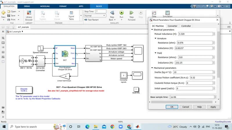
The Four-Quadrant Chopper DC Drive (DC7) block represents a four-quadrant, DC-supplied, chopper (or DC-DC PWM converter) drive for DC motors. This drive features closed-loop speed control with four-quadrant operation. The speed control loop outputs the reference armature current of the machine. Using a PI current controller, the chopper duty cycle corresponding to the commanded armature current is derived. This duty cycle is then compared with a sawtooth carrier signal to obtain the required PWM signals for the chopper.
The main advantage of this drive, compared with other DC drives, is that it can operate in all four quadrants (forward motoring, reverse regeneration, reverse motoring, and forward regeneration). In addition, due to the use of high switching frequency DC-DC converters, a lower armature current ripple (compared with thyristor-based DC drives) is obtained. However, four switching devices are required, which increases thecomplexity of the drive system.
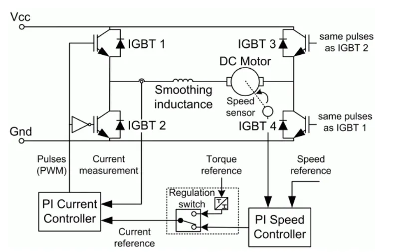
The machine is separately excited with a constant DC field voltage source. There is thus no field voltage control. By default, the field current is set to its steady-state value when a simulation is started.
The armature voltage is provided by an IGBT converter controlled by two PI regulators. The converter is fed by a constant DC voltage source. Armature current oscillations are reduced by a smoothing inductance connected in series with the armature circuit.
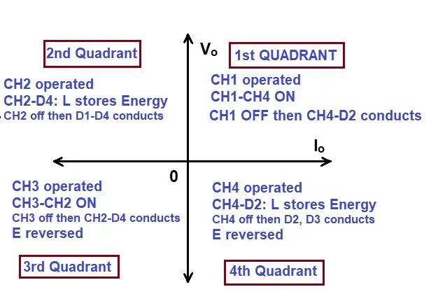
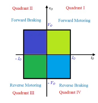
COMPARISON OF 4 QUADRANT CHOPPER AND BJT H BRIDGE:
1) the 4 quadrant chopper works in all four modes like
- forward motoring
- forward breaking
- reverse motoring
- reverse breaking
but the BJT h bridge model works on only two modes
- forward motoring
- reverse motoring
2)to change the direction of rotation of motor from forward to reverse and vice versa , the current signals get transited from one to other switch while in h bridge model, the direction of rotation of motor is changed by changing the polarity of current.
3)the 4 quadrant chopper have high switching frequency
while h bridge model have low switching frequency
4)the armature current in 4 quadrant chopper have a little spike at transition from one to other switch because of high swithing frequency while h bridge model have high spike of current.
5) the 4 quadrant chopper is generally used in industrial application while h bridge model is used in robotics.
2. Develop a 2-quadrant chopper using simulink & explain the working of the same with the relevant results. (Refer to article - Multiquadrant operation of motor )
Objective:
To create a model for control of DC motor using two quadrant type C model DC chopper.
Chopper model:
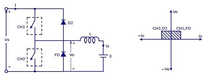
Where,
Vs=DC voltage source.
CH1= Power electronic switch 1.
CH2= Power electronic switch 2.
D2,FD = Free wheeling diodes.
L=Inductor load.
E Back emf from load.
Mode of operation:
- Here either one should be ON at a time,either CH1 or CH2.
- If CH1 is ON the current flows from source +ve to load(here DC motor),passes through L and E to -ve terminal of source.(1st quadrant)
- If CH1 is OFF the, FD diode conducts and complete the circuit (L-E-FD-L) as stored energy in inductor L.The voltage across is also positive voltage,current direction also positive.
- Now If CH2 is ON,Current flow from E(Load current) completes the circuit(L-CH2-E).
- If CH2 gets OFF,the current passes through D2 towards source completes the circuit(E-L-D2-+ve source- -ve source-E).
- In this stage regenerative breaking occurs.(2nd quadrant).
- This cycle continuous again upto stop time.
Model:
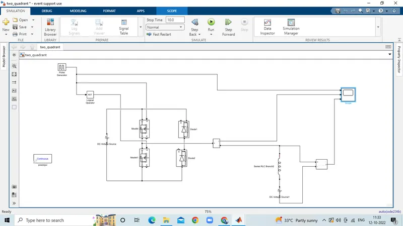
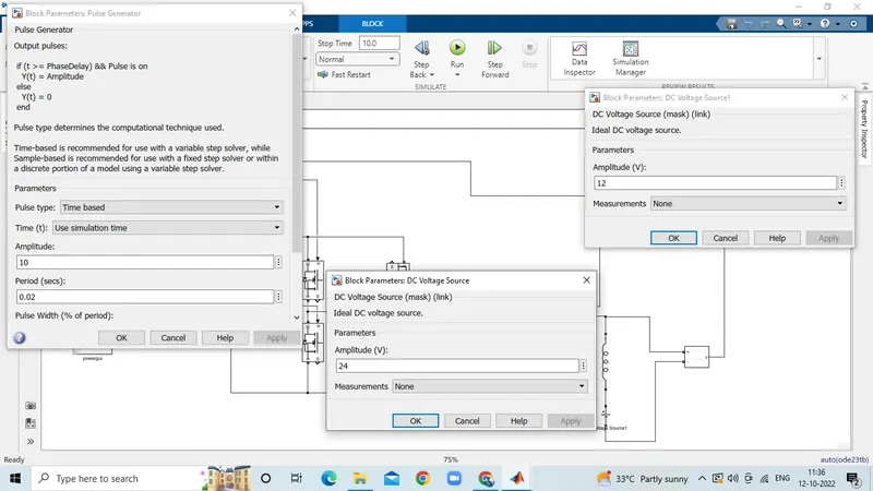
let us take two mosfet blocks and diodes blocks and connect it as shown in circuit diagram.
the dc voltage source is connected as shown.
let the voltage of dc voltage source be 24 volts.
let us consider an series RLC branch block and select inductor L . thus block works as a load.
to consider LE load ie motor load , and dc voltage source of 12 volt is also connected in series with inductor.
The pulse generator block is used to create gate pulse.
the not gate is used in the model so that the two mosfet will not get closed at the same time otherwise short circuit will occur .due to use of not gate , when one mosfet is ON the other mosfet will get off and when other mosfet is ON the first mosfet will get off .
The amplitude of pulse generator is kept 10 so that we can clearly see the pulses at scope and let period be 0.02 seconds and let pulse weidth be 50%
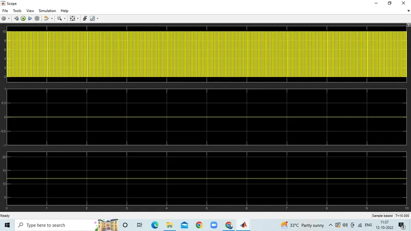
the voltage waveform is not going less than zero . the minimum value of voltage is zero and maximum value is always in the positive direction.
however in current waveform , the current increases and decreases. the current may be positive as well as negative.
and the pulse amplitude is 10 thus from pulse waveform we can see that the pulse amplitude is 10.
3. Explain in a brief about operation of BLDC motor.
BLDC motor named as brushless dc motor having high effenciency than other types of motors.This motor is also known to be synchronous motor.
Construction:
Most of the motors are having brushes in their rotor as it transfers current into the rotor circuit.But here differently rotor is placed with permanent magnet.
The stator coil is wounded with coils,they are stationary but producing variable DC voltages for rotating the permanent magnet as changing the magnetic field of stator poles continuously.
The controlling of motor is by changing the magnitude and direction of current flowing through the stator windings.
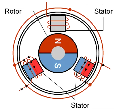
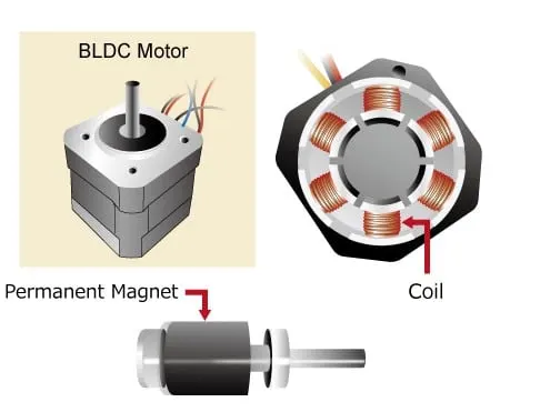
A BLDC motor with three coils on the stator will have six electrical wires (two to each coil) extending from these coils. In most implementations three of these wires will be connected internally, with the three
remaining wires extending from the motor body. Wiring in the BLDC motor case is more complicated than simply connecting the power cell’s positive and negative terminals. we will look more closely at how
these motors work in the second session of this series.
Operation of BLDC motor:
We can consider three winding trminal are comming out as U,V,W and their another ends are connected in single point as shown in below figure.The angle shift between two coils makes 120 degree.
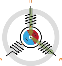
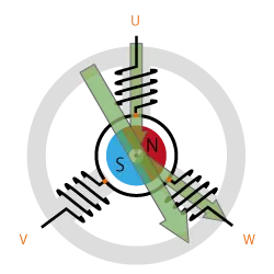
The current moves from U to W makes magnetizing the coils attracts the rotor consisting of permanent magnet makes moment as shown above to align with the resultant arrow(larger arrow).
North pole of magnet towards arrow mark of resultant arrow.
Rotation is maintained by continually switching the flux so that the permanent magnet is constantly chasing the rotating magnetic field induced by the coils. In other words, energizing of U, V, and W must be
continually switched so that the resultant flux keeps moving, producing a rotating field that continually pulls on the rotor magnet.
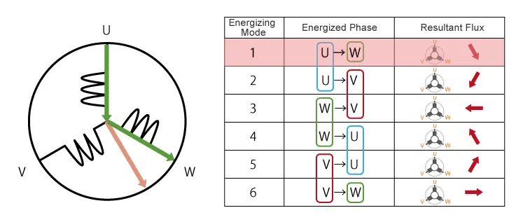
The above movement are acheived by continuous change in current direction over two poles of stator at single time.But this is slightly not continuous in their rotation.
This makes motor vibration and noice will be produced.
So, to attain smooth continuous rotation of rotor we have to control the current flow through all the three poles in same time.
As shown below we can acheive continuous change in current flow in all stator poles at same time in 120 degree phase shift.
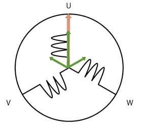
As we have seen, we drive BLDC motors by continually changing the directionality of the flux produced by the coils. The permanent magnets on the rotor continually chase the shifting rotating magnetic field,
causing the rotor to turn.
This is the working of BLDC motor.
Advantages of BLDC motor:
- One big advantage is efficiency, as these motors can control continuously at maximum rotational force (torque).
- Even small BLDC motors can deliver considerable power.
- BLDC motors can be controlled, using feedback mechanisms, to delivery precisely the desired torque and rotation speed.
- Reduce energy consumption and heat generation.
- BLDC motors also offer high durability and low electric noise generation.
- The sparks will not be produced as brushed motor between brushes and commutators.
Control of BLDC motor:
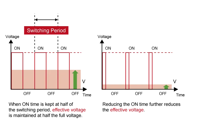
By using the inverter circuitry to also adjust the voltage into each coil, we can control the magnitude of the current.
A typical way to adjust the voltage is with pulse width modulation (PWM). We alter the voltage by lengthening or reducing the pulse ON time ( “Duty cycle”: the ON time
expressed as a ratio of the ON+OFF switching interval). Increasing the duty cycle has the same effect as raising the voltage,reducing the duty cycle has the same effect as lowering the current.
PWM can be implemented using MPUs equipped with dedicated PWM hardware. While 120-degree conductiong control only requires two-phase voltage control.
sinusoidal control uses three-phase voltage control and is considerably more complicated as appropriate inverter circuitry is therefore essential for driving BLDC motors.
CONCLUSION:
1) MATLAB demo model named ‘Speed control of a DC motor using BJT H-bridge is studied and the the armature current shoot-up is studied and ‘The Four-Quadrant Chopper DC Drive (DC7) block is also studied and Compare it with the H-bridge model
2) 2-quadrant chopper using simulink model is made and the various results obatined is studied.
3)operation of BLDC motor is studied.
REFERENCES:
https://www.edn.com/brushless-dc-motors-part-ii-control-principles/
https://www.edn.com/brushless-dc-motors-part-i-construction-and-operating-principles/
https://robu.in/brushless-dc-motor-working-principle-construction-applications/
https://www.electricaltechnology.org/2016/05/bldc-brushless-dc-motor-construction-working-principle.html
https://www.circuitstoday.com/types-of-chopper-circuits