Project - Speed Control of a Direct Current (DC) motor
1.
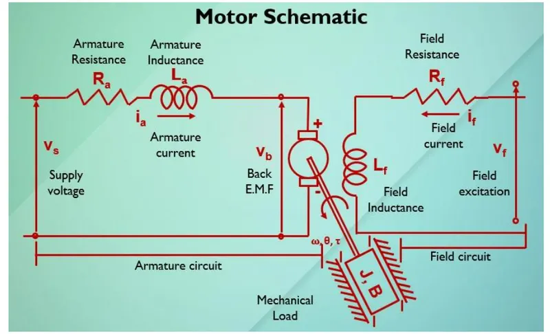
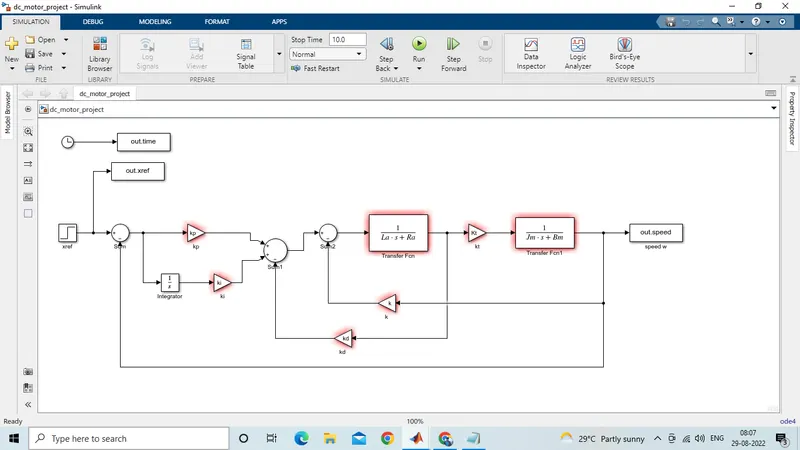
In this project, a Simulink model for the DC motor will be first developed per the schematic shown in Figure 1.
Use the Proportional, Integral, and Derivative (PID) control design knowledge gained in the training to design, develop and test a controller to maintain a desired speed for the motor.
solution:
Simulink model for dc motor
*A direct current (dc) machine can function as a generator or motor
*A dc machine has a rotor (i.e:rotating part) with an armature winding providing the electrical circuit.
*It also has a stator (i.e:stationary part) with an field winding serving as a magnet when energized.
*While operating in generator mode a prime mover is coupled to the rotor allowing into rotate in the magnetic field created by the filed winding.
* The mechanism induces a electromotive force (EMF) in the conductor mounted on the rotor and contributes to voltage generation
*While operating in motor mode, the electrical energy supplied to the armature winding and the field winding contributes to a rotating magnetic field that forces the rotor to rotate which generates a mechanical torque.
i.)mathematical modeling from the first principle
kirchoff's voltage law
Vf=RfIf+If(Dif/dt)
Vg=RaIa+La(Dia/dt)+u
Zl=Rl+Sl1
The algebraic sum of all voltage around any closed loop in a circuit is equal to zero
The relation between the generated voltage & field flux is given by
Vg=kfi(dtheta/dt)
Vg=KgIf
Here k & kg are the proportionality constant & fi is the field flux
*The open loop transfer function for the generator with a load voltage (vi) and field excitation (vf) can be derived as
Vl(s)/Vf(s)=Kg(Rl+Sli)/[(Rl+Ra)+s(Li+La)](Rf+SLf)
A propotional integral & derivative (PID) controller can be designed to maintain the desired bad voltage using appropriate field excitation
*Using kirchoff's voltage law, one can drive
Vs=RaIa+La(Dia/dt)+Vb
*Back EMF, angular velocity & torque are related
Vb=Km(dtheta/dt)
T=KTi
Here,km and kT are the back emf and torque constants respectively
*Angular velocity w=theta dot
*The open loop tranfer function for the motor with the speed (w) and supply voltage (vs) can be derives
w(s)/Vs(s)=Ktorque/JLas^2+(JRa+BLa)s+(BRa+KTKm)
*A proportional integral and derivative (PID) controller design is demonstrate to obtain the desired anguar speed using the appropriate supply voltage.
Vs = Supply Voltage
Ra = Armature Resistance
Ia = Armature Current
La = Armature Inductance
Vb = Back EMF.
Back EMF, angular velocity, and torque are related by,
Vb = Km t =kti
ii.) modeling a electrical engineering system
PID design for speed control of dc motor
Parameters
(J) Moment of inertia of the rotor 0.01 kg.m^2
(b) Motor viscous friction constant 0.1 N.m.s
(Ke) electromotive force constant 0.01 V/rad/sec
(Kt) motor torque constant 0.01 N.m/Amp
(R) Electric resistance 1 Ohm
(L) Electric inductance 0.5 H
The torque generated by a DC motor is proportional to the armature current and the strength of the magnetic field.
The open loop transfer function for the motor with the speed (w) and supply voltage (Vs) can be derived as,
A PID controller design is demonstrated to obtain the desired angular speed using the appropriate supply voltage.
For a unit step command in motor speed, the control system's output should meet the following requirements.
Settling time less than 2 seconds
Overshoot less than 5%
Steady-state error less than 1%
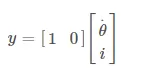
In state-space form, above can be expressed by choosing the rotational speed and electric current as the state variables.
Armature voltage is treated as the input and the rotational speed is chosen as the output.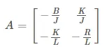




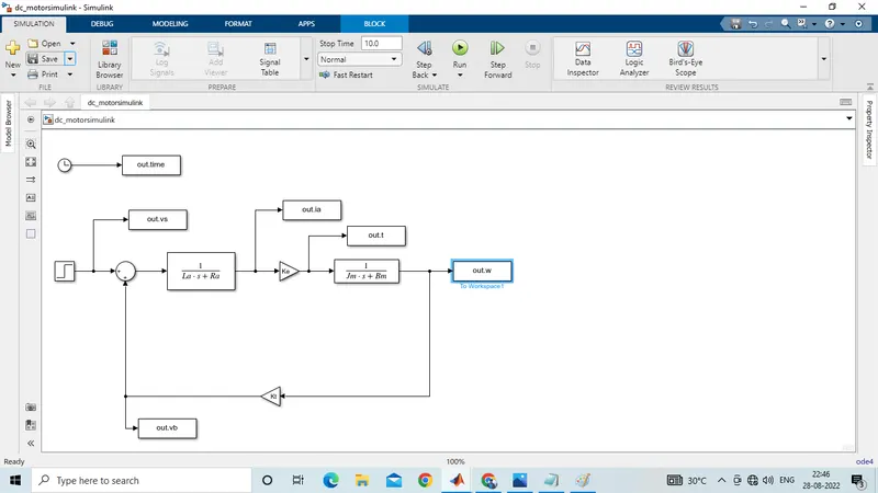
iv.)simulink based modeling
all these calculations are done in a matlab file dc motor.m
%motor design parameter
J=0.01; %motor moment of inertia Kg-m^2
B=0.1; %motor visious friction constant in N-m-s
km=0.01; %back emf constant in V/rad/s
Kt=0.01; %motor torque constant in N-M/amp
Ra=1.0; %resistance of the armature circuit in ohms
La=0.5; %inductance of the armature circuit in henry
%design of PID controller
A = [-B/J K/Jm;-k/La-Ra/La];
B = [0; 1/La];
%placement of poles
fn = 1;
wn = 2*pi*fn;
zeta = 0.5;
p1 = -zeta*wn+wn*sqrt(zeta^2-1);
p2 = -zeta*wn-wn*sqrt(zeta^2-1);
p = [p1;p2];
k = place(A,B,p);
kp = k(1);
kd = k(2);
ki = 0;
after pole placement, we get values of proportional gain kp & kd
iii.)control law design and test
v.)stability of the dynamic system
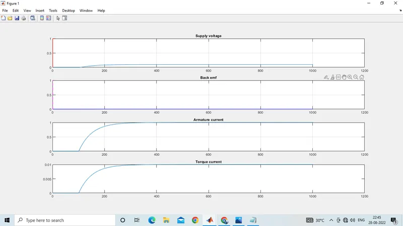
%Plot Supply Voltage and speed
subplot(411);
plot(out.w);grid;hold;
plot(out.vs,'r-');title('Supply voltage');
%Plot Back emf
subplot(412);
plot(out.vb,'b-');grid;title('Back emf');hold;
plot(out.vs,'m--');
% Plot Armature current
subplot(413);grid;
plot(out.ia);title('Armature current');grid;
%Plot Torque Current
subplot(414);grid;
plot(out.t);title('Torque current');
conclusion
This response gives the pid speed control of dc machine the various response and explained with detailed plots of various parameters of dc machine