Project 3
Design and simulation of Buck converter for Auxiliary load in EV.
- Input voltage is 48V, Output voltage is 12 V
- Load current is 10A
- Calculate Duty ratio and Load(use Resistor as Load)
- Calculate L,C
AIM: Design and simulation of Buck converter for Auxiliary load in EV.
- Input voltage is 48V, Output voltage is 12 V
- Load current is 10A
- Calculate Duty ratio and Load(use Resistor as Load)
- Calculate L,C
What is buck converter ?
A step-down DC/DC converter is a device capable of converting an unregulated input voltage into an regulated output voltage lower than the input voltage
A buck converter steps down the applied DC input voltage level directly. By directly means that buck converter is non-isolated DC converter. Non-isolated converters are ideal for all board level circuits where local conversion is required. Fax machines, scanners, Cellphones, PDAs, computers, copiers are all examples of board level circuits where conversion may require at any level inside the circuit. Hence, a buck converter converts the DC level of input voltage into other required levels.
Buck converter is having a wide range of use in low voltage low power applications. Multiphase version of buck converters can provide high current with low voltage. Therefore, it can be used for low voltage high power applications. This article will discuss both low voltage low power converter and low voltage high power converter
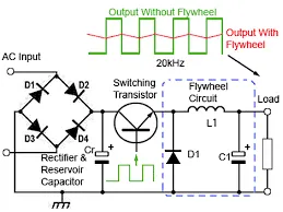
This buck converter having following controlling uits
1)Switching power supply unit which, can turn ON/OFF switching elements that can be turned ON/OFF at high frequency to convert a dc input voltage Vin into a dc output voltage Vout.
2)Control unit, which is used to control the ON/OFF operation of the switching element. We use MOSFET as switching element where the pulse generator is a control unit for MOSFET.
3)Inductor - It stores the energy during ON period & dissipates during OFF period.
4)Capacitor- It bypass the ripple content in the output voltage
5)Freewheeling diode- It freewheel the current through the resistor from the inductor & circuilate it in circuit during OFF period.
6)Load Resistor- Across it we can measure the output voltage & current through it
CALCULATION:
Given data,
Input Voltage Vin = 48 V
Output Voltage Vout = 12 V
Load current iL = 10 A
Mathematical Formulae-
Output Voltage = Load resistor * Load current
Vout = R * iL
Load Resistor = Output Voltage / Load current
%Duty ratio D = (Vout / Vin) * 100
Minimum Inductance Lmin = [(1-D)*R] / (2*f)
Maximum Inductance L = 1.25 * Lmin
Capacitance C = (1-D) / (8*L*r*f^2)
Ripple factor r = Change in output voltage / rated output voltage
Assumptions:
1)The switching frequency(f) of the buck convertes is taken to be 40 KHz.
2)Ripple factor (r) is assume to be 0.5%
Calculations-
Load resistor R = Vout / iL = 12/10 = 1.2 ohm
Duty ratio(cycle) D = Vout / Vin = 12 / 48 = 0.25
% D = = 0.25*100 = 25%
Minimum Inductance Lmin = [(1-D)*R] / (2*f)
Lmin = [(1.025)*1.2] / (2*40000) = 11.25 micro henry
Maximum Inductance L = 1.25 * Lmin = 14 micro henry
L = 1.25 * Lmin = 14 micro henry.
Capacitance C = (1-D) / (8*L*r*f^2)
C = (1-0.25) / (8*14*10^-6*r*40000^2) = 837 micro farad
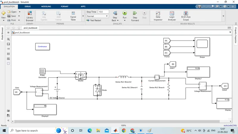
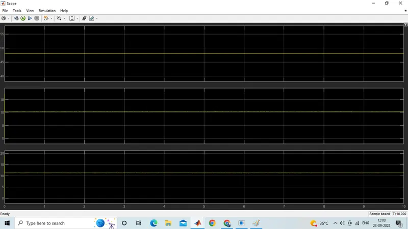
observing the waveform & display block we get the required output voltage= 11.32V, Load current=10.29A In the observation little bit variation which may due to chemistry of battery & losses.
plotting
CONCLUSION:
We have Design and simulation of Buck converter for Auxiliary load in EV.
- Input voltage is 48V, Output voltage is 12 V
- Load current is 10A