DC Motor Control Simulation using Power Converters
Power Electronics
Power electronics is the application of semiconductor devices such as transistors, diodes and integrated circuits (ICs) to the control and conversion of electric voltage.
In order to achieve the purpose of voltage electronics, the devices are made to work as nothing more than a switch. All the voltage electronic devices act as a switch and have two modes, i.e. ON and OFF.
The voltage electronic devices alone are not that useful in practical applications and hence require to be designed with a circuit along with other supporting components. These supporting components are like the decision-making part which controls the voltage electronic switches in order to achieve the desired output.
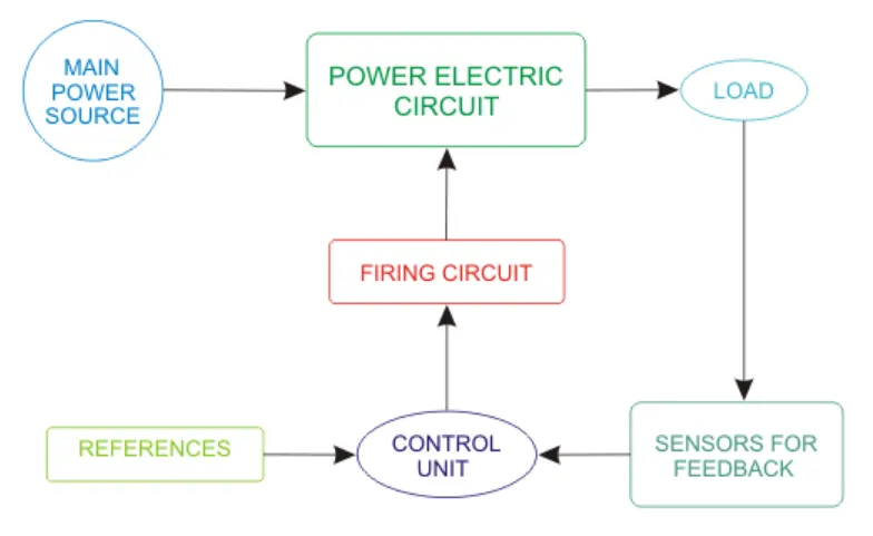
The Control Unit takes the output feedback from sensors and compares it with references and accordingly gives input to the firing circuit. Firing circuit is basically a pulse generating circuit which gives pulse output in a fashion so as to control the voltage electronic switches in the main circuit block.
Majorly there are five types of voltage electronic circuits, each having different purpose-
- Rectifiers – converts fixed AC to variable DC (such as half-wave rectifiers or full-wave rectifiers)
- Choppers – converts fixed DC to variable DC
- Inverters – converts DC to AC having a variable amplitude and variable frequency
- Voltage Regulators – converts fixed AC to variable AC at a same input frequency
- Cycloconverters – converts fixed AC to AC with variable frequency
Commonly used voltage electronic devices:-
Bipolar Junction Transistor (BJT)
A Bipolar Junction Transistor (also known as a BJT or BJT Transistor) is a three-terminal semiconductor device consisting of two p-n junctions which are able to amplify or magnify a signal. It is a current controlled device.
There are two types of bipolar junction transistors –
- NPN transistors are constructed by sandwiching a P-type semiconductor between two N-type semiconductors. The NPN transistor behaves like two PN junction diodes connected back to back.
- PNP transistors are constructed by sandwiching an N-type semiconductor between two P-type semiconductors. The PNP transistor behaves like two PN junction diodes connected back to back.
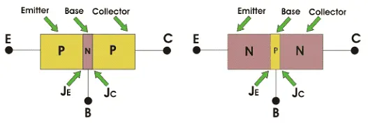
BJT has three parts named emitter, base and collector. JE and JC represent the junction of emitter and junction of collector respectively. Now initially it is sufficient for us to know that the emitter-base junction is forward biased and collector-base junctions are reverse biased.
Metal Oxide Semiconductor Field Effect Transistor (MOSFET)
The MOSFET is a capacitor operated transistor device. The capacitor plays an essential role for operating a MOSFET.
It is a voltage-controlled device. The voltage of the covered gate determines the electrical conductivity of the device, this ability to change conductivity with the amount of applied voltage can be used for amplifying or switching electronic signals.
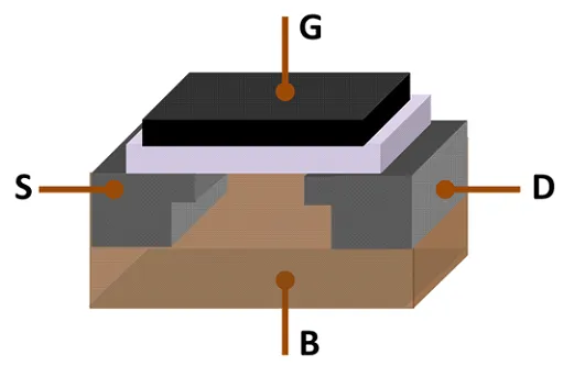
MOSFET, showing gate (G), body (B), source (S) and drain (D) terminals. The gate is separated from the body by an insulating layer (pink).
Insulated Gate Bipolar Transistor (IGBT)
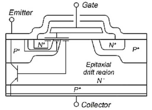
An insulated-gate bipolar transistor (IGBT) is a three-terminal voltage semiconductor device primarily used as an electronic switch which, as it was developed, came to combine high efficiency and fast switching.IGBT has PMOSFET like input characteristics and Power BJT like output characteristics and hence its symbol is also an amalgamation of the symbols of the two parent devices. The three terminals of IGBT are Gate, Collector and Emitter.
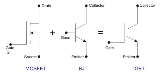
Cross-section of a typical IGBT showing the internal connection of MOSFET and bipolar device
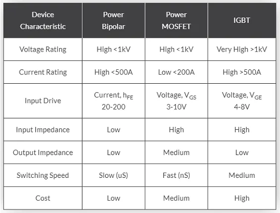
IGBT Comparison Table
Thyristor or Silicon Controlled Rectifier (SCR)
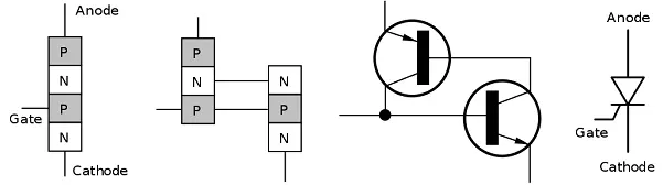
Silicon Controlled Rectifier is a unidirectional semiconductor device made of silicon. SCR is a three-terminal, four-layer semiconductor device consisting of alternate layers of p-type and n-type material.
Q1. Run MATLAB demo ‘Speed control of a DC motor using BJT H-bridge’. Modify the model such that the armature current doesn’t shoot up when the motor changes direction from forward to reverse.
Speed control of a DC motor using BJT H-bridge
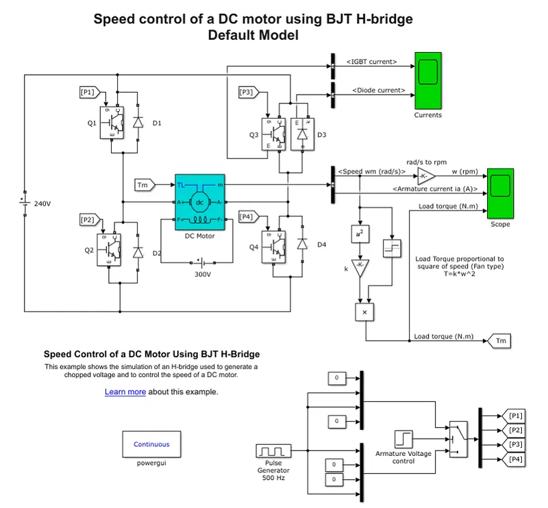
The Bipolar Junction Transistor (BJT) when used for voltage switching applications, operates as an IGBT. When it is conducting (BJT operating in the saturated region), a forward voltage Vf is developed between collector and emitter (in the range of 1 V). Therefore, the IGBT block can be used to model the BJT device.
The IGBT block does not simulate the gate current controlling the BJT or IGBT. The switch is controlled by a signal (1/0). The DC motor uses the preset model (5 HP 24V 1750 rpm). It simulates a fan type load (where Load torque is proportional to square of speed). The armature mean voltage can be varied from 0 to 240 V when the duty cycle (specified in the Pulse Generator block) is varied from 0 to 100%.
Model
Working
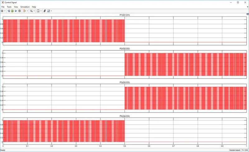
The H-bridge consists of four BJT/Diode pairs (BJT simulated by IGBT models). Two transistors are switched simultaneously: Q1 and Q4 or Q2 and Q3. When Q1 and Q4 are fired, a positive voltage is applied to the motor and diodes D2-D3 operate as free-wheeling diodes when Q1 and Q4 are switched off. When Q2 and Q3 are fired, a negative voltage is applied to the motor and diodes D1-D4 operate as free-wheeling diodes when Q2 and Q3 are switched off.
Control Signal
Input Voltage Signal
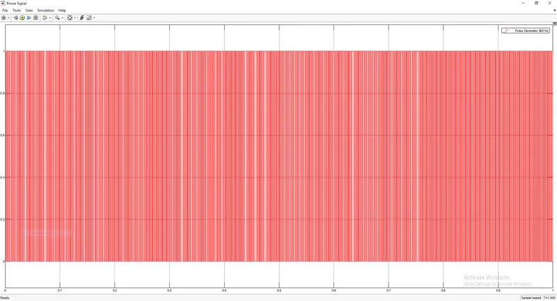
A DC voltage signal with a duty cycle of 75% (75% of 240V=180V) and a frequency of 500Hz is applied using a pulse generator.
Results
The current flowing in the armature coil is directly proportional to the potential difference and inversely proportional to the armature resistance.
`I_a=V/R_a`
The potential difference is the algebraic sum of supply voltage Es and the back Emf.
`I_a=(E_(s)-E_(b))/R_a`
Here the supply voltage remains constant, and the back-EMF depends upon the magnetic field strength and angular velocity(rpm).
`E_b=K_mPhiw`
When the motor starts to rotate the rpm(angular velocity) is motor is nearly zero thus the back-EMF is nearly zero and armature current is given by
`I_(a-st arti ng)=E_s/R_a`
As the motor starts to rotate the rpm(angular velocity) increases and reaches equilibrium, similar corresponding to the rpm, the back-EMF also increases and reaches equilibrium with the rpm. Now the armature current is given by
`I_(a-equilibrium)=(E_s-E_b)/R_a`
Thus `I_(a-st arti ng)>I_(a-equilibrium)`
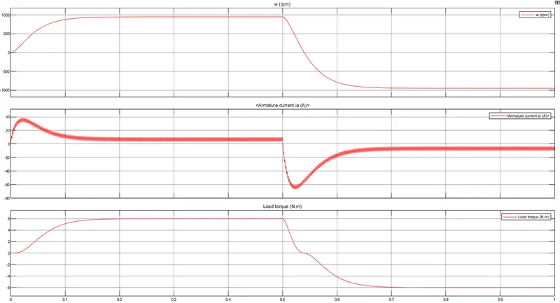
When the Voltage Supply is reversed at t=0.5, due to inertia the motor keeps to rotate in the direction opposite to the supplied voltage. Now the back_EMF and the supply voltage act in the same direction and the armature current is given by
`I_(a-reverse)=(-E_s-E_b)/R_a`
The magnitude of the `I_(a-reverse)` is greater than `I_(a-equilibrium)` and `I_(a-st arti ng)`. Hence an armature current shoot-up is seen when the voltage supply is reversed.
Methods to Control Armature Current Shoot-Up
Back-EMF is directly proportional to the motor constant, magnetic field strength, and angular velocity(rpm). The equation for back-Emf is given by
`E_b=K_mPhiw`
To reduce the Back-Emf we can reduce Magnetic Field Intensity and angular velocity(rpm) of the motor.
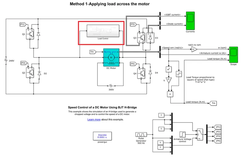
Method-1 Applying Load across the Armature Coil
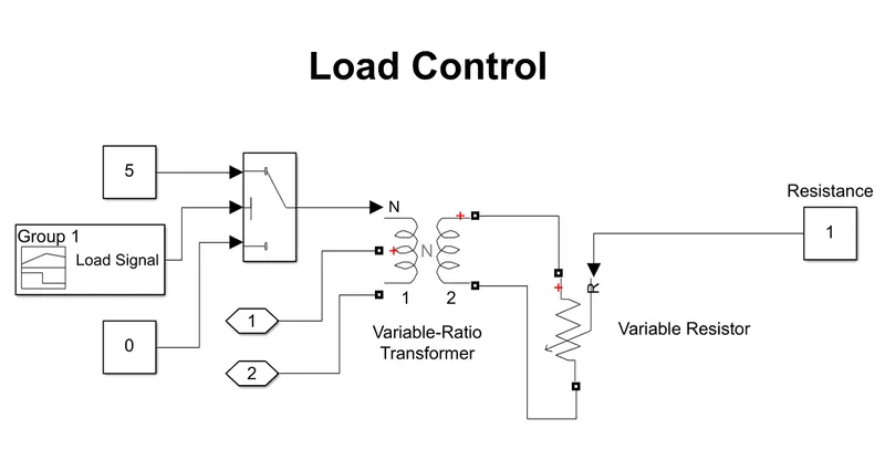
An inductive load is applied across the motor using the Variable Ratio Transformer and a nominal resistance is applied and the circuit is completed.
Load Control Subsystem
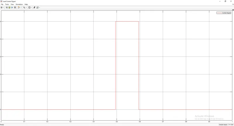
Load Control Signal
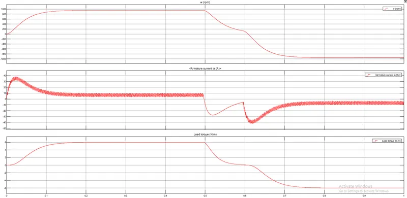
Result
A load is applied across the motor to draw the current from the armature coil when the voltage supply is reversed, this reduces the rpm and the current induced due back-EMF.
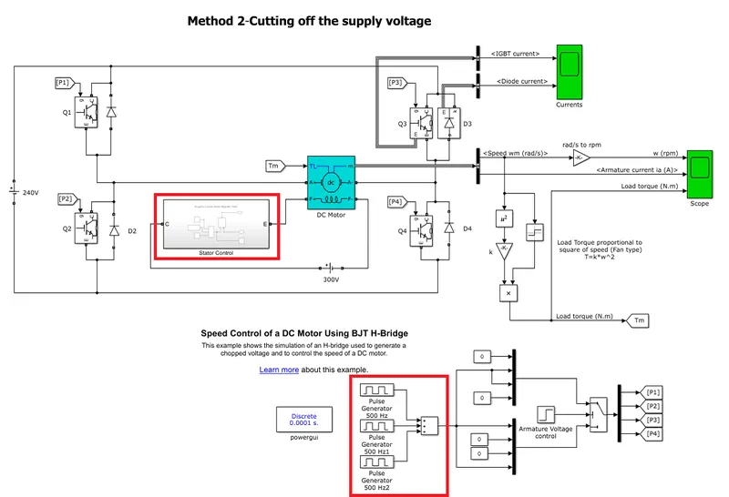
Method-2 Reducing the Magnetic Field and RPM by Cutting Off Supply Voltage
Using the phase delay option and addition block we make the voltage supply to be zero for a fraction of a second and similarly the voltage supply for the stator coil is cut-off, thus magnetic field intensity is made zero.
By voltage supply cut-off we subject the rotor to friction or damping, hence reducing the rpm.
Stator Control Subsystem
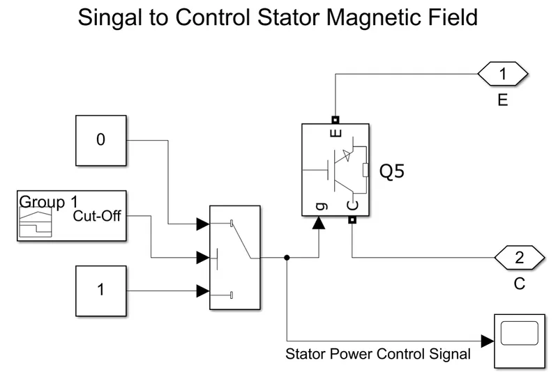
Stator Coil Input Voltage Control Signal
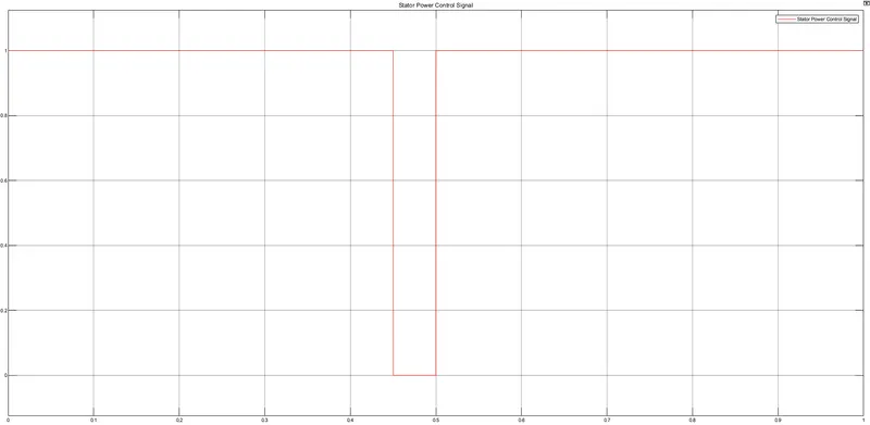
Modified Input Voltage Signal
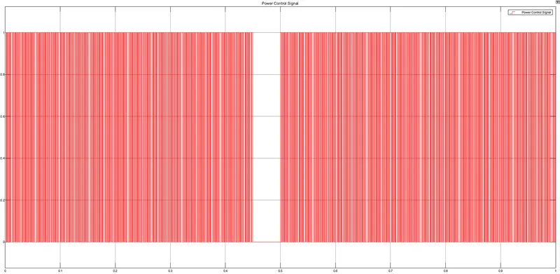
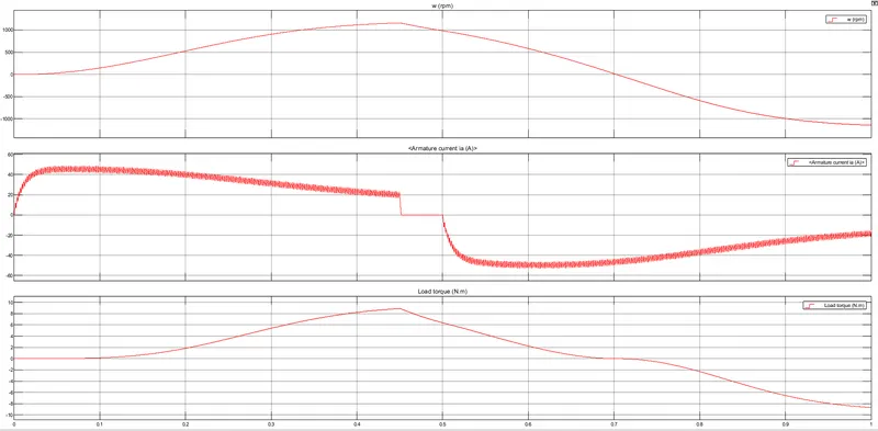
Results
Due to voltage cutoff, the rpm of the motor is reduced and when the voltage is reversed the back-EMF is induced is less, thus reducing the armature current shoot-up.
Q2. Comparing 'The Four-Quadrant Chopper DC Drive (DC7)' block with the 'H-bridge' model.
H-Bridge
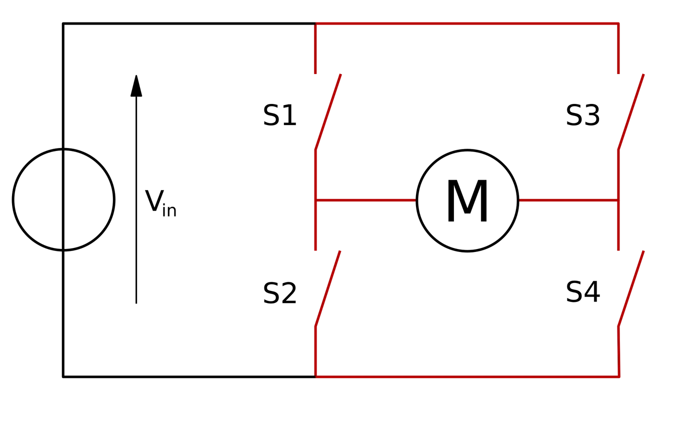
An H-bridge is an electronic circuit that switches the polarity of a voltage applied to a load.
Working
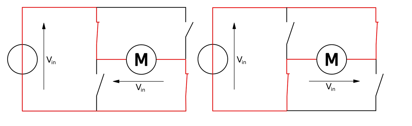
The term H bridge is derived from the typical graphical representation of such a circuit. An H bridge is built with four switches (solid-state or mechanical). When the switches S1 and S4 (according to the first figure) are closed (and S2 and S3 are open) a positive voltage will be applied across the motor. By opening S1 and S4 switches and closing S2 and S3 switches, this voltage is reversed, allowing reverse operation of the motor.
Using the nomenclature above, the switches S1 and S2 should never be closed at the same time, as this would cause a short circuit on the input voltage source. The same applies to the switches S3 and S4. This condition is known as shoot-through.
Chopper
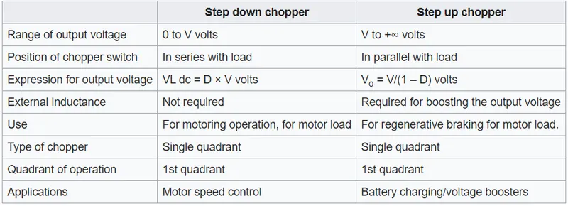
A chopper is a device that converts fixed DC input to a variable DC output voltage directly. Choppers are used in various types of electronic switching devices and circuits used in power control and signal applications such as electric vehicles, traction motor control, voltage regulators, etc.
Types of Chopper:-
1. Step-up chopper
2. Step-down chopper
A chopper can work in any of the four quadrants. we can classify chopper circuits according to their working in any of these four quadrants as type A, type B, type C, type D, and type E.
1.Type A Chopper
The Type-A Chopper is also known as the first quadrant chopper as it allows operation only in the first quadrant.
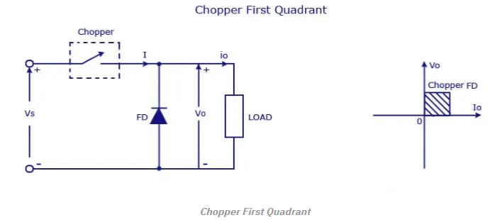
When the chopper is on, v0 = VS as a result, and the current flows in the direction of the load. But when the chopper is off v0 is zero but I0 continues to flow in the same direction through the freewheeling diode FD, thus the average value of voltage and current say V0 and I0 will be always positive as shown in the graph. In type A chopper the power flow will be always from source to the load. As the average voltage V0 is less than the dc input voltage Vs.
2. Type B Chopper
The type B Chopper is also called the second quadrant chopper as it operates in called second quadrant.
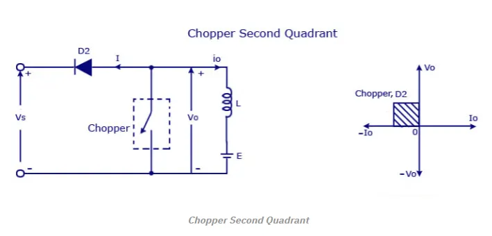
When the chopper is on, v0 is zero but the load voltage E drives the current through the inductor L and the chopper, L stores the energy during the time Ton of the chopper. When the chopper is off, v0 =( E+ L . di/dt ) will be more than the source voltage Vs. Because of this the diode D2 will be forward biased and begins conducting and hence the power starts flowing to the source. No matter the chopper is on or off the current I0 will be flowing out of the load and is treated negative. Since VO is positive and the current I0 is negative, the direction of power flow will be from load to source. The load voltage V0 = (E+L .di/dt ) will be more than the voltage Vs so the type B chopper is also known as a step-up chopper.
Type -C chopper
The type C Chopper is also called Two-quadrant type-A Chopper as Type C chopper is obtained by connecting type –A and type –B choppers in parallel. We will always get a positive output voltage V0 as the freewheeling diode FD is present across the load. When the chopper is on the freewheeling diode starts conducting and the output voltage v0 will be equal to Vs. The direction of the load current i0 will be reversed. The current i0 will be flowing towards the source and it will be positive regardless of the chopper is on or the FD conducts. The load current will be negative if the chopper is or the diode D2 conducts. We can say the chopper and FD operate together as type-A chopper in the first quadrant. In the second quadrant, the chopper and D2 will operate together as type –B chopper.
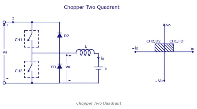
The average voltage will be always positive but the average load current might be positive or negative. The power flow may be from the first quadrant operation ie from source to load or from load to source like the second quadrant operation. The two choppers should not be turned on simultaneously as the combined action may cause a short circuit in supply lines. For regenerative braking and motoring, this type of chopper configuration is used.
Type D Chopper
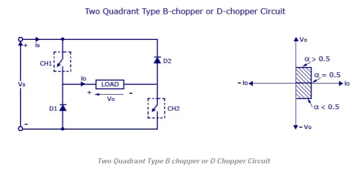
The circuit diagram of the type D chopper is shown in the above figure. When the two choppers are on the output voltage v0 will be equal to Vs. When v0 = – Vs the two choppers will be off but both the diodes D1 and D2 will start conducting. V0 the average output voltage will be positive when the choppers turn-on the time Ton will be more than the turn-off time Toff its shown in the waveform below. As the diodes and choppers conduct current only in one direction the direction of load current will be always positive.
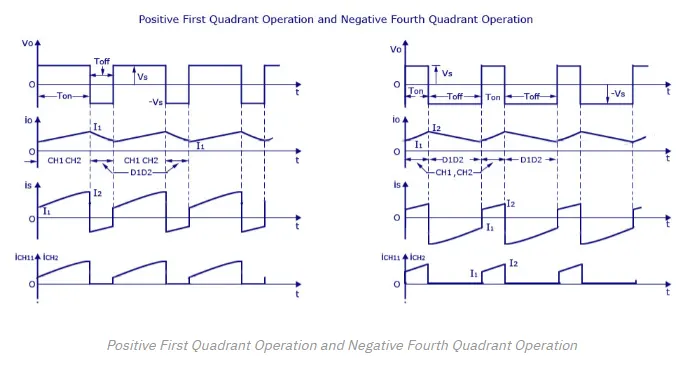
The power flows from source to load as the average values of both v0 and i0 is positive. From the waveform, it is seen that the average value of V0 is positive thus the fourth quadrant operation of type D chopper is obtained.
Type E
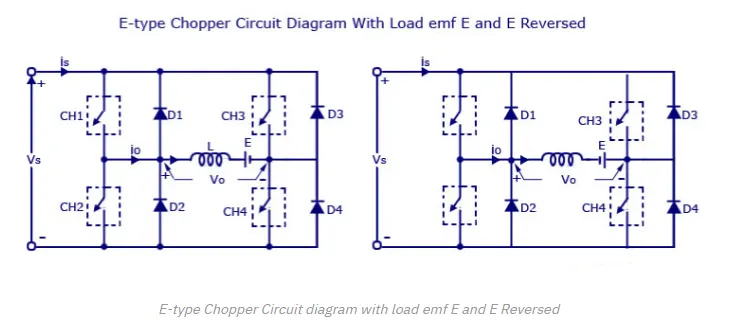
Type E or the fourth quadrant chopper consists of four semiconductor switches and four diodes arranged in antiparallel. The 4 choppers are numbered according to which quadrant they belong. Their operation will be in each quadrant and the corresponding chopper only be active in its quadrant.
i. First Quadrant
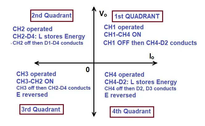
During the first quadrant operation, the chopper CH4 will be on. Chopper CH3 will be off and CH1 will be operated. AS the CH1 and CH4 is on the load voltage v0 will be equal to the source voltage Vs and the load current i0 will begin to flow. v0 and i0 will be positive as the first quadrant operation is taking place. As soon as the chopper CH1 is turned off, the positive current freewheels through CH4 and the diode D2. The type E chopper acts as a step-down chopper in the first quadrant.
ii. Second Quadrant
In this case, the chopper CH2 will be operational and the other three are kept off. As CH2 is on negative current will starts flowing through the inductor L, CH2, E and D4. Energy is stored in the inductor L as the chopper CH2 is on. When CH2 is off the current will be fed back to the source through the diodes D1 and D4. Here (E+L.di/dt) will be more than the source voltage Vs. In the second quadrant, the chopper will act as a step-up chopper as the power is fed back from load to source.
iii. Third Quadrant
In third quadrant operation, CH1 will be kept off, CH2 will be on and CH3 is operated. For this quadrant working the polarity of the load should be reversed. As the chopper CH3 is on, the load gets connected to the source Vs and v0 and i0 will be negative and the third quadrant operation will take place. This chopper acts as a step-down chopper.
iv. Fourth Quadrant
CH4 will be operated and CH1, CH2 and CH3 will be off. When the chopper CH4 is turned on positive current starts to flow through CH4, D2, E and the inductor L will store energy. As the CH4 is turned off the current is feedback to the source through the diodes D2 and D3, the operation will be in fourth quadrant as the load voltage is negative but the load current is positive. The chopper acts as a step-up chopper as the power is fed back from load to source.
The Four-Quadrant Chopper DC Drive (DC7)
The Four-Quadrant Chopper DC Drive (DC7) block represents a four-quadrant, DC-supplied, chopper (or DC-DC PWM converter) drive for DC motors. This drive features closed-loop speed control with the four-quadrant operation. The speed control loop outputs the reference armature current of the machine. Using a PI current controller, the chopper duty cycle corresponding to the commanded armature current is derived. This duty cycle is then compared with a sawtooth carrier signal to obtain the required PWM signals for the chopper. Implement four-quadrant chopper DC drive.
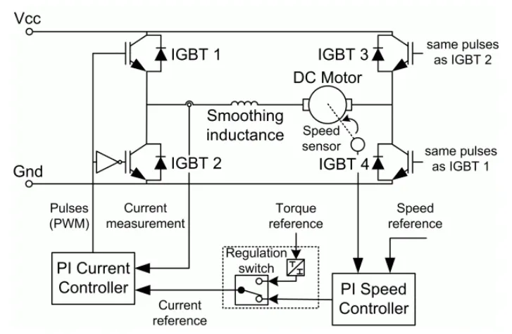
The Four-Quadrant Chopper DC Drive block uses these blocks from the Electric Drives/Fundamental Drive Blocks library:
-
Speed Controller (DC)
-
Regulation Switch
-
Current Controller (DC)
-
Chopper
Comparison between The Four-Quadrant Chopper DC Drive (DC7) VS 'H-bridge'
|
The Four-Quadrant Chopper DC Drive (DC7) |
H-bridge |
|
|
Q3. Make a suitable EV model using the DC7 block and make a report.
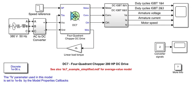
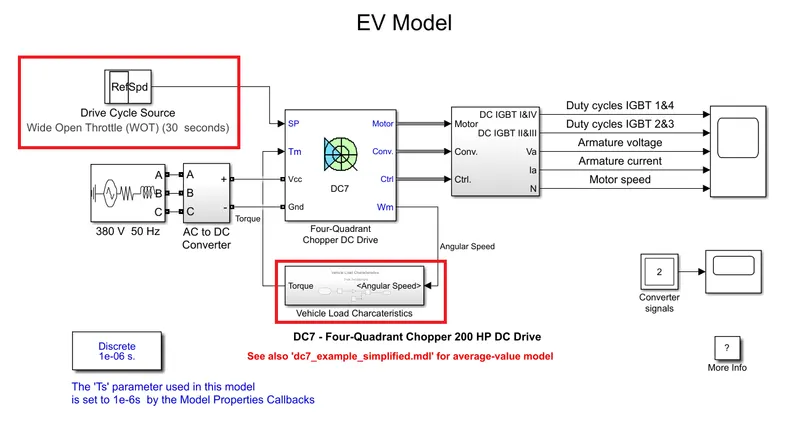
The 200 HP DC motor is separately excited with a constant 150 V DC field voltage source. The armature voltage is provided by an IGBT converter controlled by two PI regulators. The converter is fed by a 515 V DC bus obtained by rectification of a 380 V AC 50 Hz voltage source. In order to limit the DC bus voltage during dynamic braking mode, a braking chopper has been added between the diode rectifier and the DC7 block.
The first regulator is a speed regulator, followed by a current regulator. The speed regulator outputs the armature current reference (in p.u.) used by the current controller in order to obtain the electromagnetic torque needed to reach the desired speed. The speed reference change rate follows acceleration and deceleration ramps in order to avoid sudden reference changes that could cause armature over-current and destabilize the system. The current regulator controls the armature current by computing the appropriate duty ratios of the 5 kHz pulses of the four IGBT devices (Pulse Width Modulation). For proper system behavior, the instantaneous pulse values of IGBT devices 1 and 4 are opposite to those of IGBT devices 2 and 3. This generates the average armature voltage needed to obtain the desired armature current. In order to limit the amplitude of the current oscillations, a smoothing inductance is placed in series with the armature circuit.
To convert 'The Four-Quadrant Chopper DC Drive (DC7) block' into an EV Model we need to add the following components:-
1. Drive Cycle
A driving cycle is a series of data points representing the speed of a vehicle versus time.
2. Torque Speed Characteristics
Torque speed characteristics is the relation between the torque and speed of a vehicle based on the different forces acting on the vehicle due to mass, velocity, road gradient, etc.
The Traction or tractive force is the force used to generate motion between a body and a tangential surface. It is the force generated by the powertrain of the vehicle to overcome all the external and internal forces resisting the motion.
The Traction Force is given by
Fte=Frr+Fad+Fhc+Fla+Fwa">`F_(te)=F_(rr)+F_(ad)+F_(hc)+F_(la)+F_(wa)` where
Frr">`F_(rr` is the Rolling Resistance Force
F(ad)">`F_(ad` is the Aero Dynamic Drag Force
Fhc">`F_(hc` is Hill Climb Force
Fla">`F_(la` is Force required for Linear Acceleration
Fwa">`F_(wa` is force required to give Angular Acceleration to motor
Traction Force required can be given by the equation
`F_(te)=μ_(rr)⋅m⋅g+1/2⋅ρ⋅Cd⋅v2+m*g*sintheta+m⋅a+I⋅G^2/(η_g⋅r^2)⋅a`
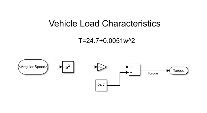
Based on the above equation, the Speed Torque Characteristic of a vehicle can be expressed as
`T=24.7+0.0051*w^2`
EV Model
Vehicle Load Model
Results
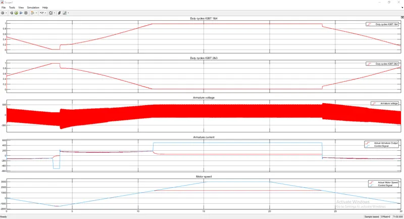
The working of The Four-Quadrant Chopper DC Drive (DC7) is similar to the Type E chopper, where IGBT 1 & 4 work in a loop operated at the same time and the IGBT 2 and 3 work together. The duty cycle of the two loops formed are complementary in nature, that is when IGBT 1 & 4 is having a duty cycle of 40% then IGBT 2 & 3 will a duty cycle of 60% and vice versa. This is shown in the first 2 plots from the scope.
The third plot shows the voltage applied as per our input need, negative when we require motoring and positive when we require forward motoring.
The fourth and fifth plot compares the control signal and the actual signal. The fourth plot compares the amount of current flowing through the armature coil vs the control signal. Here we can see that our motor is less powered compared to our requirements as the control signal have higher values bust due to vehicle design restrictions they are not full filled.
Similarly, we can see in the fifth plot where control signal rpm is the desired rpm but the actual vary as per the vehicle design restrictions.
References
1. https://www.electrical4u.com/page/2/?s=voltage+transistor
2. https://en.wikipedia.org/wiki/MOSFET
3. https://www.electronics-tutorials.ws/power/insulated-gate-bipolar-transistor.html
4. https://en.wikipedia.org/wiki/Thyristor
5. https://en.wikipedia.org/wiki/H-bridge
6. https://en.wikipedia.org/wiki/Chopper_(electronics)
7. https://www.circuitstoday.com/types-of-chopper-circuits
8. https://in.mathworks.com/help/physmod/sps/ug/dc7-four-quadrant-chopper-200-hp-dc-drive.html