Week-7 Challenge: DC Motor Control
Aim:
To understand an develop the DC motor control.
Objective:
- A. Explain a MATLAB demo model named ‘Speed control of a DC motor using BJT H-bridge’.
B. Comment on the armature current shoot-up from the scope results.
C. Refer to the help section of ‘The Four-Quadrant Chopper DC Drive (DC7) block’. Compare it with the H-bridge model.
-
Develop a 2-quadrant chopper using Simulink & explain the working of the same with the relevant results. (Refer to an article - Multiquadrant operation of motor )
-
Explain in a brief about operation of BLDC motor.
Theory:
Power Modules &Power Switches
When it comes to EV application, controlling the Speed of the Motor mainly depends on controlling the Voltage & Current flowing to the Motor. To ensure a rotating field in the motor continuously, flux has to be switched continuously by controlling the direction and timing of the Current in to the coil.
In order to achieve this Controllers/Inverters are used to adjust the Voltage in the coil and to control the magnitude of current.
PWM (Pulse Width Modulation) is the technique incorporated in Power switches which alters the Voltage level by lengthening or reducing the Pulse ON time
Q 1:
A. Explains a MATLAB demo model named ‘Speed control of a DC motor using BJT H-bridge
Operations:
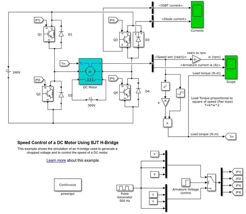
In the above circuit, the input voltage is generated from the pulse generator where the amount of supply and duty cycle is assigned in the pulse generator.
Then the switch block is connected to pulse generator through an armature voltage control block.
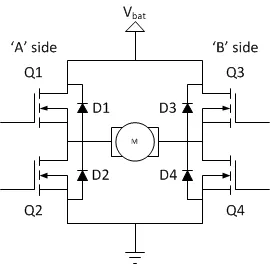
The H - bridge consists of 4 BJT/ Diode pairs. Two transistors are switched simultaneously: Q1 and Q4 or Q2 and Q3.
When Q1 and Q4 are fired a positive voltage is applied to motor and diodes D2-D3 operate as free-wheeling diodes when Q1 and Q4 are switched off.
When Q2 and Q3 are fired a negative voltage is applied to motor and diodes D1-D4 operate as free-wheeling diodes when Q2 and Q3 are switched off.
A switch block at bottom of circuit splits the power supply into 4 parts namely are p1, p2, p3, and p4
Switching:
Q1 and Q4 - Forward motoring
Q2 and Q3 - Reverse motoring
Torque for mechanical input of DC motor also switched by goto and from.
The output of the DC motor is connected with the BUS sector whereas the speed is plotted in the scope. A conversion of speed for red/sec to rpm is between the BUS sector and the scope using the converter block
B. Comment on the armature current shoot-up from the scope results.
Output:
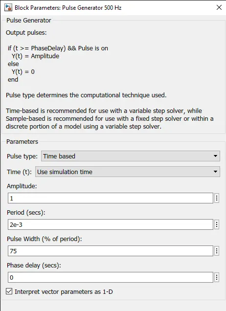
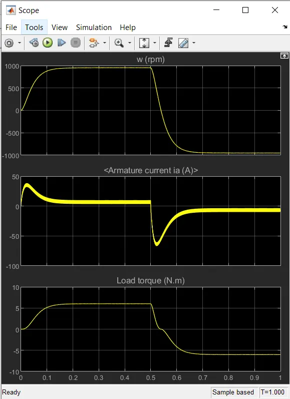
The pulse width was set at 75 in the pulse generator
Output:
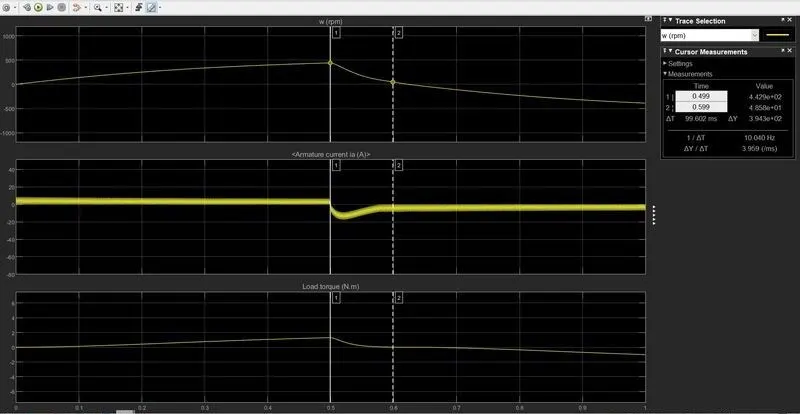
During the 0.5 sec of time D3 switch is ON that are given according to the pulse generator and after the time period of 0.5 sec D3 switch is OFF and IGBT current is acted after 0.5 sec and Q3 switch remains ON
Changing the plus generator value:
By opening the pulse generator we can change the pulse width i.e the input value to whatever desire. So here we change the value to 50%.
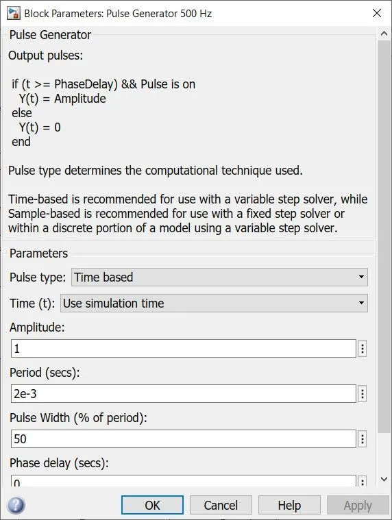
In this above scope, a flow of armature current is displayed and speed load torque is also displayed.
The change is made in pulse width as 50% from the pulse generator and results are shown that voltage fluctuation is held in starting point of forwarding reverse state.
The sudden fluctuation is reduced in this experiment by reducing the pulse width of the input supply
A change is also held speed and load torque where the constant level of speed and torque is acted in above scope compare with the previous 75% of the pulse width.
A time period of forwarding and reverse action is maintained as same as the previous Duty cycle
C. Refer to the help section of ‘The Four-Quadrant Chopper DC Drive (DC7) block
Four Quadrant Operation of DC motor means that the machine operates in four quadrants. They are forward motoring, Forward braking, reverse motoring and reverse braking.
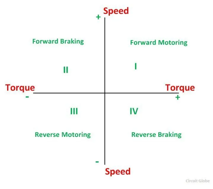
In the I quadrant power developed is positive and the machine is working as a motor supplying mechanical energy. The I (first) quadrant operation is called Forward Motoring. II (second) quadrant operation is known as Braking. In this quadrant the direction of rotation is positive, and the torque is negative, and thus, the machine operates as a generator developing a negative torque, which opposes the motion.
The kinetic energy of the rotating parts is available as electrical energy which may be supplied back to the mains. In dynamic braking dissipated the energy is dissipated in the resistance. The III (third) quadrant operation is known as the reverse motoring. The motor works, in the reverse direction. Both the speed and the torque have negative values while the power is positive
In the IV (fourth) quadrant, the torque is positive, and the speed is negative. This quadrant corresponds to braking in the reverse motoring mode
FOUR QUADRANT CHOPPER 200HP DC DRIVE:
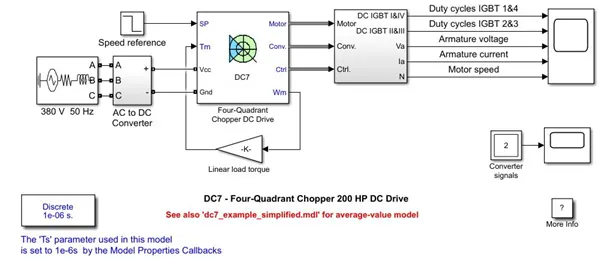
The reference speed is provided using step input and a 3 phase AC source is provided. As the 4 quadrant runs in varying DC supply, a AC to DC converter is used.
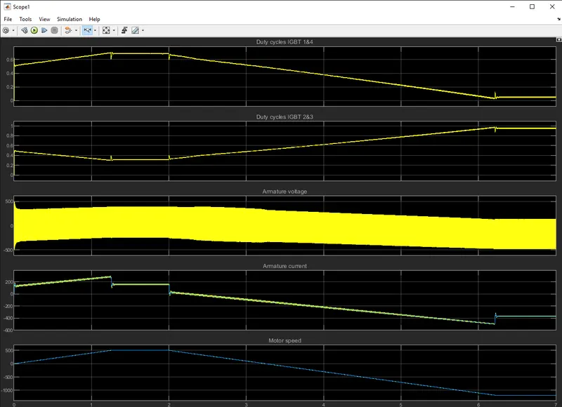
The 200 HP DC motor is separately excited with a constant 150 V DC field voltage source. The armature voltage is provided by an IGBT converter controlled by two PI regulators. The converter is fed by a 515 V DC bus obtained by rectification of a 380 V AC 50 Hz voltage source. In order to limit the DC bus voltage during dynamic braking mode, a braking chopper has been added between the diode rectifier and the DC7 block.
The first regulator is a speed regulator, followed by a current regulator. The speed regulator outputs the armature current reference (in p.u.) used by the current controller in order to obtain the electromagnetic torque needed to reach the desired speed.
The current regulator controls the armature current by computing the appropriate duty ratios of the 5 kHz pulses of the four IGBT devices (Pulse Width Modulation).
For proper system behaviour, the instantaneous pulse values of IGBT devices 1 and 4 are opposite to those of IGBT devices 2 and 3. This generates the average armature voltage needed to obtain the desired armature current. In order to limit the amplitude of the
Compare it with H-bridge model:
| BJT H-BRIDGE DRIVE | FOUR QUADRANT CHOPPER DRIVE |
| It's used for changing the direction of the motor(forward and reverse) | Here the motor can be operated in four different modes (forward motoring & braking, reverse motoring and braking) |
| Regenearative braking is unavailable | Regenerative braking can be achieved |
| The source is fixed DC supply | The source is an AC supply whicj can be recified to varying DC supply |
| The motor speed reference cannot be fed | The motor speed reference can be fed |
| The armature ccurrent shoot up during phase transition | The armature current doesn't shoot up to value of BJT H-Bridge but for a negligible value |
| Used in robotics | Used in commercial applications |
H bridge:
Question 2:
Develop a 2-quadrant chopper using Simulink & explain the working of the same with the relevant results.
- Class - C chopper is a Two quadrant Chopper.
- Its functions in the 1st and 2nd quadrants.
- In class C chopper, output voltage is always positive and output current can be positive or negative.
- This type of chopper obtains by connecting class-A and class - B chopper in parallel.
Simulink model:
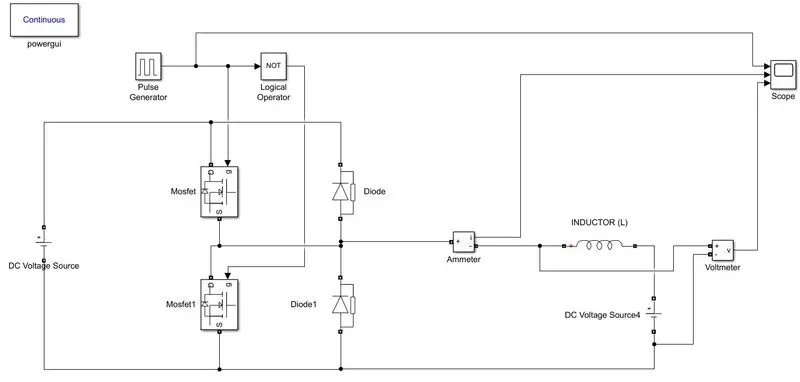
Blocks used:
- Power GUI
- Voltage measurement Block
- Current measurement block
- DC voltage source
- Mosfet
- Pulse generator
- Diode
- Series RLC band
- Logical Operator
Working:
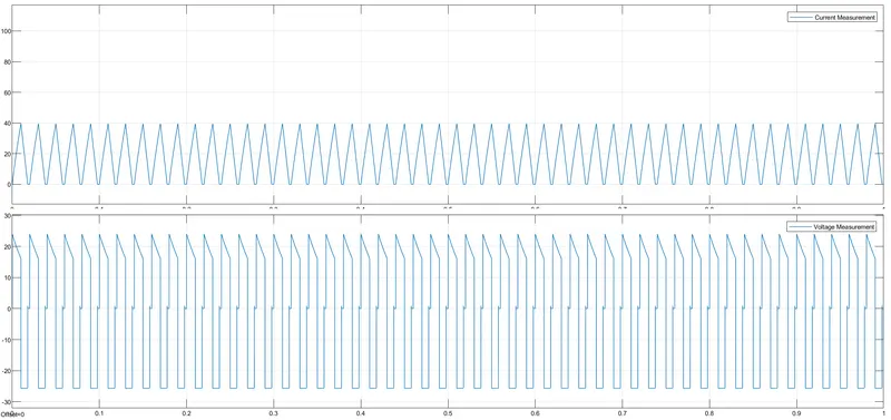
The Two - quadrant chopper DC drive block represents a two-quadrant, DC - supplied, chopper drive for DC motor.
This drive features closed-loop speed control with a two-quadrant operation. The speed control loop output the reference armature current of the machine.
Using a PI current controller, the chopper duty cycle corresponding to the commanded armature current is derived.
This duty cycle is then compared with a sawtooth carrier signal, to obtain the required PWM signals for the chopper.
The main advantages of this drive, compared with other DC drives, are its implementation simplicity and the that it can operate in two quadrants.
In addition due to the use of a high switching frequency DC-DC converter, a lower armature current ripple is obtained. However, for all two-quadrant DC drives reversible and regenerative operations, which are required in most DC drives cannot be obtained
Question 3:
Explain in a brief about operation of BLDC motor
A brushless DC electric motor (BLDC motor or BL motor), also known as an electronically commutated motor (ECM or EC motor) or synchronous DC motor, is a Synchronous motor using a direct current (DC) electric power supply.
It uses an electronic close loop control to switch DC currents to the motor winding producing magnetic fields which effectively rotate in space and which the permanent magnet rotor follows. The controller adjusts the phase and amplitude of the DC pulses to control the speed and torque of the motor.
This control system is an alternative to the mechanical commutator (brushes) used in many conventional electric motors
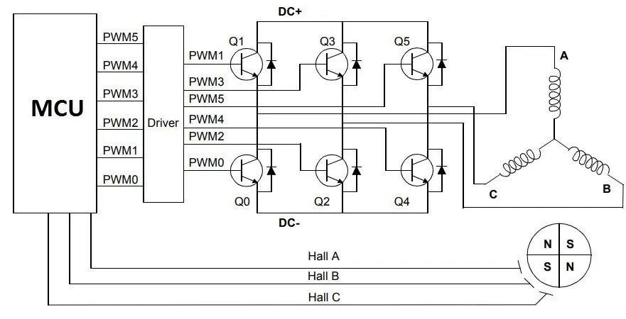
Simple model circuit of BLDC
Working of BLDC:
Consider the following setup of three windings in the stator designated A, B, and C. For the sake of understanding, let us replace the rotor with a single magnet.
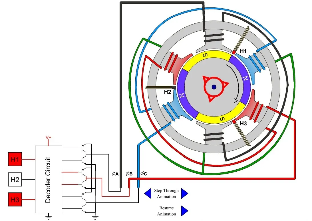
The brushless DC motor has only two basic parts are rotor and the stator. The rotor is the rotating part and has rotor magnets whereas stator is the stationary part and contains stator windings. In BLDC permanent magnets are attached in the rotor and move the electromagnets to the stator.
The high power transistors are used to activate electromagnets for the shaft turns. The controller performs power distribution by using a solid-state circuit.
Applications of Brushless DC motor:
Brushless DC motors (BLDC) use for a wide variety of application requirements such as varying loads, constant loads and positioning applications in the fields of industrial control, automotive, aviation, automation systems, health care equipments etc.
- Computer hard drives and DVD/CD players.
- Electric vehicles, hybrid vehicles, and electric bicycles.
- Industrial robots, CNC machine tools, and simple belt driven systems.
- Washing machines, compressors and dryers.
- Fans, pumps and blowers
Conclusion / Result
We can conclude that we have understood the significance and importance of the DC motor control, the working and construction of the BLDC motor is successfully verified