Week-7 Challenge: DC Motor Control
Objective:
1. A. Explain a Matlab demo model named 'Speed control of a DC motor using BJT H-bridge'.
B. Comment on the armature current shoot-up from the scope results.
C. Refer to the help section of "The Four _-quadrant Chopper Dc Drive (DC&) block'. Compare it with the H-bridge model.
2. Develop a 2-quadrant chopper using Simulink & explain the working of the same with relevant results. (Refer to the article -Multiquadrant operation of the motor)
3. explain in a brief the operation of the BLDC motor.
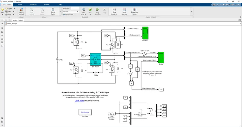
1. A.Explain a Matlab demo model named 'Speed control of a DC motor using BJT H-Bridge'.
BJT - Bipolar Junction Transistor
The Bipolar junction Transistor (BJT) When used for power switching applications, operates as an IGBT. When it is conducting (BJT operating in the saturated region), a forward voltage Vf is developed between collector and emitter (in the range of 1V)
The IGBT block does not simulate the gate current controlling the BJT or IGBT. The DC motor uses the present model (5HP 24V 1750 rpm). It simulates a fan-type load (where load torque is proportional to the square of speed). The armature means voltage can be varied from 0 to 240 V when the duty cycle (specified in the pulse generator block) is varied from 0 to 100%.
H-Bridge :
In general, H-bridge is a rather simple circuit, containing four switchings, containing four switching elements, with the load at the center, in an H-like configuration.
The H-bridge consists of four BJT / Diode pairs (BJT simulated By IGBT models). Two transistors are switched simultaneously: Q1 and Q4 or Q2 and Q3. When Q1 and Q4 are fired, a positive voltage is applied to the motor, and diodes D2-D3 operate as free-wheeling diodes when Q1 and Q4 are switched off. When Q2 and Q3 are fired, a negative voltage is applied to the motor, and diodes D1-D4 operate as free-wheeling diodes when Q2 and Q3 are switched off.
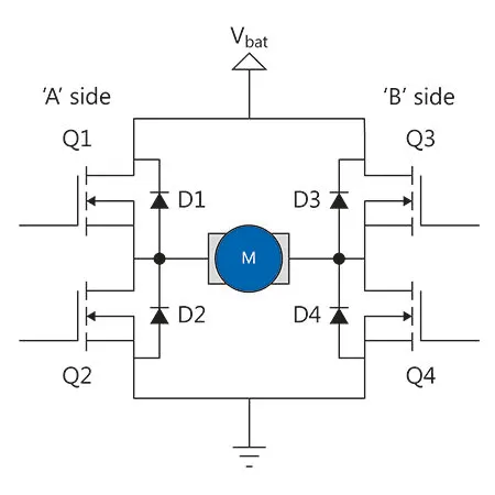
An H-bridge is essentially four switches that allow the polarity of the supply applied to a motor to be attached both ways round. Thus, the motor can be driven both clockwise and anticlockwise. It consists of a pair of high and low side switches with the motor connected between the two pairs. The engagement of the switches has to be carefully implemented as enabling a high and low side pair results in a short-circuit of the power source, something that rarely ends well.
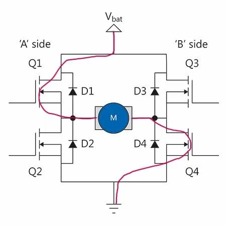
when the current flows from the battery to Q1(D1) and gets into the motor and moved to Q4(D4) and gets grounded. now the motor gets rotated in a clockwise direction.
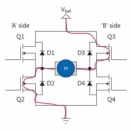
When the current flows from the battery to Q3(D3) and gets towards the motor and to Q2(D2) and gets grounded. Now the motor gets charged and starts rotating in the anticlockwise direction
Simulation:
The motor starts in the opposite direction with a duty cycle of 75%(mean DC voltage of 180V) At t=0.5sec., the armature voltage is suddenly reversed and the motor runs in the negative direction.
Scope :
The scope shows motor speed, Armature current, load torque and 'current' shows current flowing in BJT and diode D3
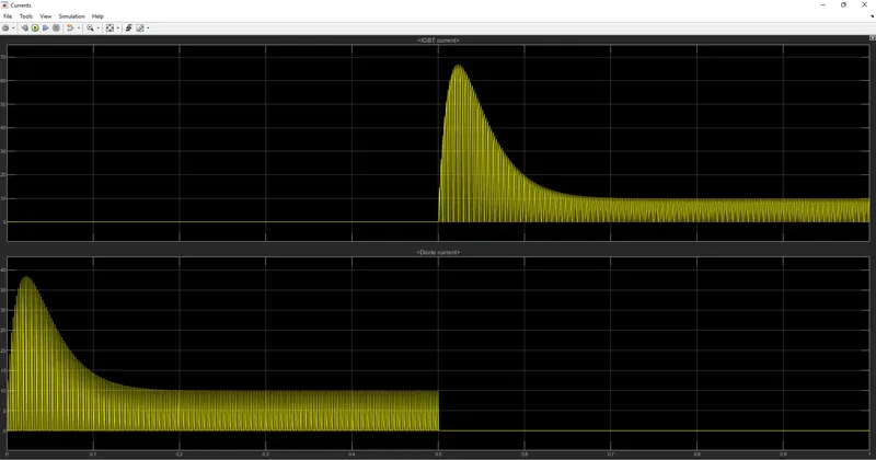
this figure shows IGBT current and Diode current
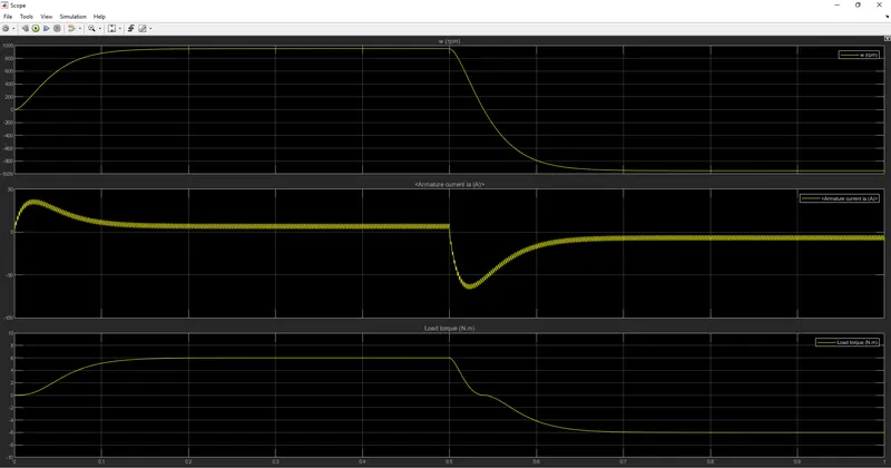
1.B.Comment on the armature current shoot-up from the scope results:

when the switch gets close the voltage becomes zero the armature current suddenly gets rises from 0 to 40 to its peak. it becomes normalized.

The blue marked line shows up transitions .which causes the thermal causes in the armature current. when the switch opens the current will be in the negative quadrant.
1. C. Refer to the help section of the 'Four quadrant chopper DC drive(DC7) block. Compare it with the H-bridge model:
Four quadrant DC drive (DC7) block:
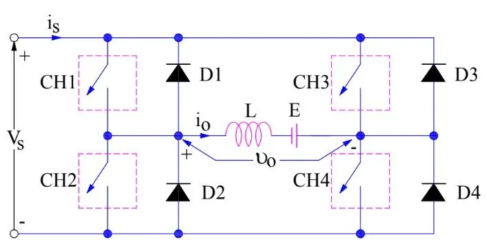
This picture is taken for reference from www. electricalbaba.com
First Quadrant :
For the first quadrant operation, CH4 is kept ON, CH3 is kept OFF and CH1 is operated. when both CH1 & CH4 are ON simultaneously, the load gets directly connected to the source and hence the output voltage becomes equal to the source voltage. This essentially means that V0 = vs. it may be noted that the load current flows from source to load as shown by the direction of io.
When CH1 is switched OFF, the load current free wheels through CH4 and D2.During this period, the load voltage and current remain positive. Thus, both the output voltage Vs and load current io is positive, and hence, the operation of choppers is in the first quadrant. it may be noted that the class-E chopper operates as a step-down chopper in case.
Second Quadrant operation:
In the second quadrant operation, CH2 is operated while keeping the CH1, CH3 & CH4 OFF. When CH2 is ON, the DC source in the load drives current through CH2, D4, E, and L. Inductor L stores energy during the ON period of CH2. When CH2 is turned OFF, the current is fed back to the source throughD1, D4. Since the current is fed back to the source, This simply means that load is transferring power to the source. Kindly read Step_up chopper for detailed analysis and better understanding.
Third Quadrant Operation:
To obtain the third quadrant, both the load voltage and load current should be negative. The current and voltage are assumed positive if their directions match what is shown in the circuit diagram. If the direction is opposite to what is shown in the diagram, it is considered negative. One important thing to notice is that the polarity of emf E in load must be reversed to have a third quadrant operation.
For the third quadrant operation, CH1 is kept off, CH2 is kept ON and CH3 is operated. When CH3 is ON, the load gets connected to the source and hence load voltage is equal to source voltage. but carefully observe that the polarity of load voltage vo is opposite.
Fourth Quadrant Operation:
To obtain a fourth quadrant operation, CH4 is operated while keeping CH1, CH2, and CH3 OFF. The polarity of load emf E needs to be reversed in this case too like the third quadrant operation.
When CH4 is turned ON, positive current flows through CH4, D2, L, and E.Inductance L stores energy during the time CH4 is ON. When Ch4 is made OFF, the current is fed back to the source through diodes D2 and D3. Here load voltage is negative but the load current is always positive. This leads to chopper operation in four quadrants. Here, power is fed back to the source from the load, and the chopper acts as a step-up chopper.
FIRST QUADRANT: CH1-OPERATED,
CH1, CH4 -ON,
CH1 OFF THEN CH4-D2 CONDUCTS
SECOND QUADRANT: CH2 OPERATED
CH2-D4:L STORES ENERGY
CH2 OFF THEN D1-D4 CONDUCTS
THIRD QUADRANT: CH3 OPERATED
CH3-CH2 ON
CH3 OFF THEN CH2-D4 CONDUCTS
E REVERSED
FOURTH QUADRANT: CH4 OPERATED
CH4-D2: L STORES ENERGY
CH4 OFF THEN D2, D3 CONDUCTS
E REVERSED
| FOUR QUADRANT CHOPPER DC DRIVE | H-Bridgit |
| It consists of four operations. forward motoring, reverse motoring, forward braking, and reversbraking | It consist of two operations. clockwise and anti-clockwise of motor rotation |
| continuous signal | discrete signal |
2. Develop a 2-quadrant chopper using Simulink & explain the working of same with reverent results:
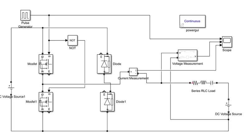
blocks to be needed
pulse generator
Mosfet
Diode
Voltage source
logical operator (NOT)
Current measurement
Voltage measurement
Series RLC load
Powerful
Scope
building of 2_quadrant chopper we need two MOSFETs which is acts as a gate and two diodes.
pulse generator is directly connected to the scope.
MOSFET has three connections. now one of the sides of both MOSFETs is connected to the pulse generator.
one of the side two diodes is connected to the voltage source.
now the second end is connected to the current measurement block.
current measurement has dual ends. one of the ends is connected to voltage measurement and another end is connected to the series RLC load
Now the results can be obtained.
3. Operation of Brushless DC motor:
What is a brushless DC motor:
A brushless DC motor, BLDC accomplishes commutation electronically using rotor position feedback to determine when to switch the current. The BLDC motor is electronically commutated by power switches instead of brushes.
Construction:
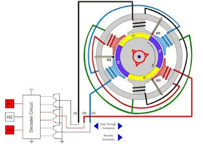
A BLDC has no brushes and commutator for having unidirectional torque rather integrated inverter/switching circuit is used to achieve unidirectional torque. That is why these motors are, also referred to as ELECTRONICALLY COMMUTATED MOTORS.
Like any other electric motor, a BLDC motor also has a stator and rotor.
BLDC Stator:
There are three types of BLDC motor:
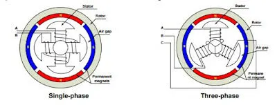
Single - phase
Two-phase
three-phase
The stator for each type has the same number of windings. The single-phase and Three-phase motors are the most widely used. The simplified cross-section of a single-phase and a three-phase BLDC motor. The rotor has permanent magnets to form two magnetic pole pairs and surrounds the stator, which has the windings
Rotor:
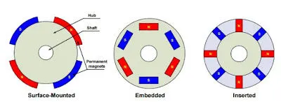
A rotor consists of a shaft and a hub with permanent magnets arranged to dorm between two to eight pole pairs that alternate between the north and south poles.
WORKING:
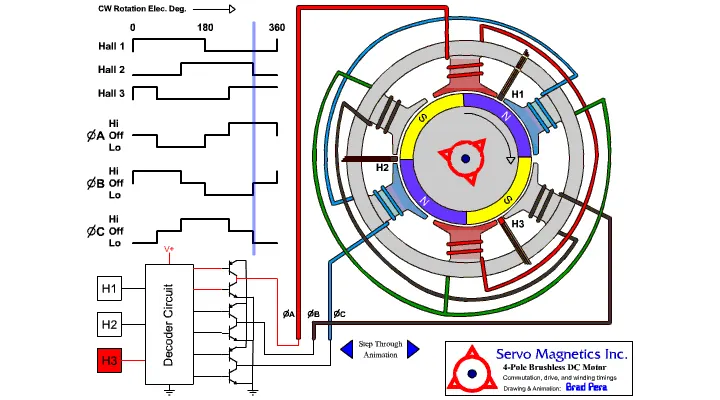
BLDC motor operation is based on the attraction or repulsion between magnetic poles. The process starts when the current flows through one of the three stator windings and generates a magnetic pole that attracts the closest permanent magnet of the opposite pole.
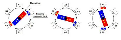
The rotor will move if the current shifts to an adjusting winding. Sequentially charging each winding will cause the rotor to follow in a rotating field. The torque in this example depends on the current amplitude and the number of turns on the stator windings, the strength and size of the permanent magnets, the air gap between the rotor and the windings, and the length of the rotating arm.
Advantages of BLDC Motor:
compared with a brushed DC motor or an induction motor, the BLDC motor has many advantages:
Higher efficiency and reliability
Lower acoustic noise
Smaller and lighter
Greater dynamic response
Better speed versus torque characteristics
Higher speed range
Longer life
REFERENCE: electricalbaba.com/brushless-dc-bldc-motor/