Week-6 Challenge: EV Drivetrain
1. What type of power converters circuits are employed in both Electric and hybrid Electric vehicle :
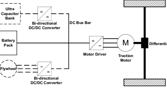
Powertrain block diagram of Electric Vehicle
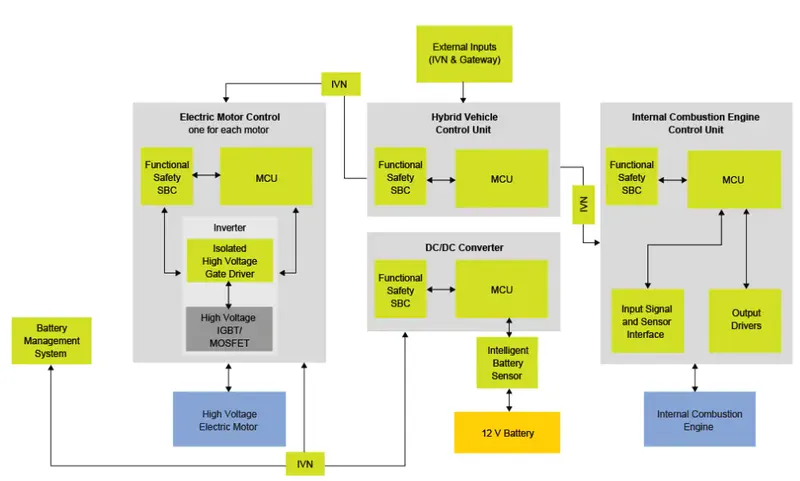
Powertrain block diagram of Hybrid electric vehicle
DC to DC converters:
- Many DC-operated applications need different levels of DC voltage from a fixed DC source. The vehicle requires variable speed, so a power conversion device is needed.
- A DC chopper is a static device that converts a fixed input DC voltage to variable DC output or a fixed DC output of a different magnitude (which can be lower or higher) than the input value.
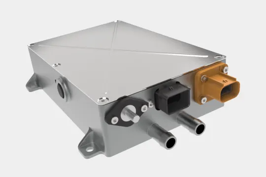
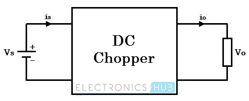
- This chopper circuit is connected between the DC input source and DC load. This chopper consists of power electronics switching devices such as thyristors which are connected in such a way that they produce the required voltage to the load.
- The output voltage is controlled by adjusting the ON time of the thyristor (or switch) which in turn changes the width of the DC voltage pulse at the output. This method of switching is called pulse width modulation (PWM) control.
- The output of the chopper can be less or greater than the input and also it can be fixed or variable. These can be unidirectional or bidirectional devices based on the application it is intended for.
- DC choppers are mainly used in DC drives,i.e, ELECTRICAL VEHICLES, AND HYBRID ELECTRIC VEHICLES.
- There are two types of DC to DC converter:
- STEP-DOWN CONVERTER OR BUCK CONVERTER
- STEP-UP CONVERTER OR BOOST CONVERTER
- BUCK-BOOST CONVERTER
STEP-DOWN CONVERTER OR BUCK CONVERTER:
- A step-down convertor produces an average output voltage lower than the input DC voltage.
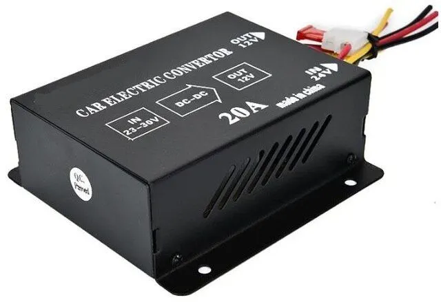
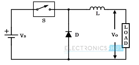
- This converter steps down the voltage from the input of 23v-30v to the output voltage of 12v.
- Here the switching component is a thyristor that switches the input voltage to the load when it is triggered at particular instants.
- This diode acts as a free-wheeling diode that allows the load current to flow through it when the thyristor is turned OFF. If this diode is absent, a high induced EMF in inductance may cause damage to the switching diode.
- The average output voltage of the converter is varied by controlling turn ON/OFF periods of thyristors. When thyristors are turned ON, the output voltage is zero.
- The output voltage is equal to (TON/ T) vin. so, by controlling the duty ratio K=(TON/T), the output voltage will be increased.
STEP-UP UPCONVERTER OR BOOST CONVERTER
- In this converter, the output voltage is always greater than the input voltage.
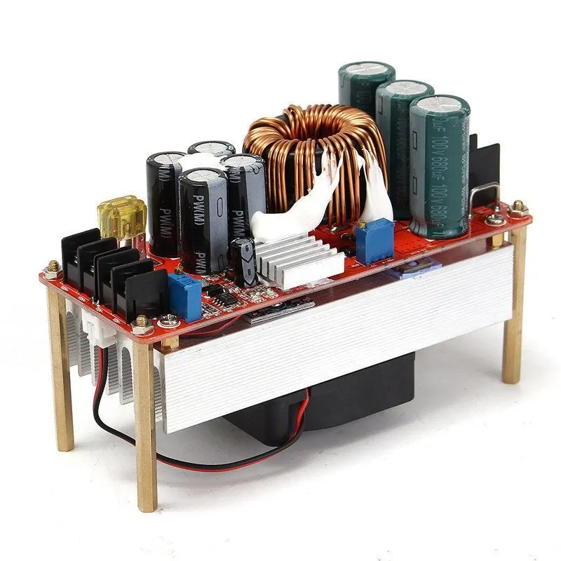
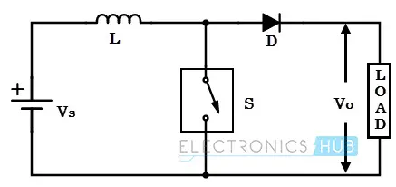
- Here also a switch is used, which is connected in parallel with the load. This switch is a thyristor or an SCR.
- As similar to the buck converter, a diode is placed in series with the load that allows the load current to flow when the thyristor is turned OFF.
- When the thyristor is turned ON, the diode is reverse-biased and hence it isolates the load circuit from the source.
- So the inductor charges to the maximum input voltage source.
- When the thyristor is turned OFF, the load gets the voltage from the input as well as from the inductor.
- So the voltage appearing across the converter output will be more than the input.
- Here the output voltage is equal to(1/1 - d) times the input voltage, where d is the duty ratio (TON / T).
- By varying this duty ratio, the output voltage will be varied till the load gets desired voltage.
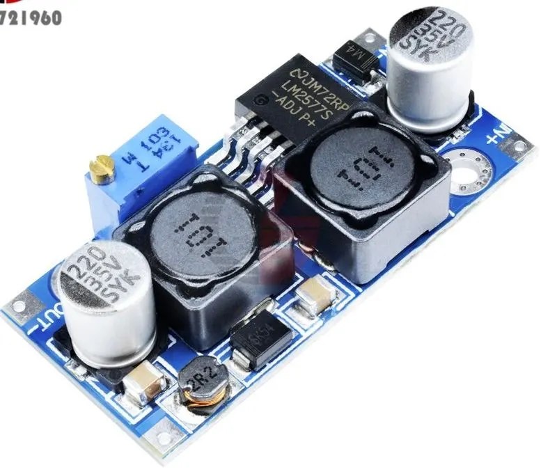
BUCK BOOST CONVERTER:
- This converter can be used both in step-down and step-up modes by continuously adjusting its duty cycle.
- Along with an inductor and diode, the additional capacitor is connected in parallel with this circuit.
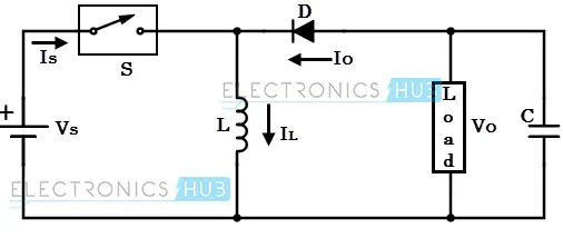
- When the thyristor is turned ON, the supply current flows to the inductor through the thyristor and induces the voltage inductor.
- when the thyristor is OFF, the current in the inductor tends to decrease with the induced emf reversing polarity.
- The output voltage of this converter remains constant as the capacitor is connected across the load.
- By varying the value of duty ratio to a certain value, the output voltage is lower than the input voltage, typically in the range 0≥k>0.5, thus a buck converter.
- And the output is higher than the input voltage if the duty ratio is in the range of 0.5>k≥1, thus acting as a boost converter
2. To calculate the EV steady state speed if the duty cycle is 70%:
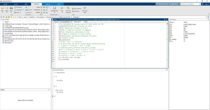
Matlab code :
% To calculate EV steady state if the duty cycle is 70%
v_battery = 71; % battery voltage in volts
Va = 72 ; % Armature voltage in volts
ia = 400; %armature current in ampere
Ra = 0.5; %armature resistance in ohm
k = 0.7; %motor constant in volts seconds
f = 400; %chopper switching frequency in hertz
d = 0.7; % duty cycle
v=v_battery*d;
% T_veh = 24.7 + 0.0051w^2;
% we know that the motor torque-speed characteristics
% T_motor = (v*k)/ra - (k^2 *2)/ra
% equating motor velocity and motor torque
%24.7 + 0.0051ω`ω`^2 = 50.4 *0.7/0.5 - (0.7^2 *)/0.5
%0.0051ω^2 = 70.56-24.7 - (0.49 *w)/0.5
%0.0051ω^2 = 45.86 - 0.98ω
%0.0051ω^2 0.98ω - 45.86 = 0
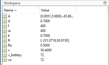
A = [0.0051ω^2 + 0.98ω - 45.86];
R = roots(A)
R =
-2331.0718
38.9150
ignoring negative value and taking the positive value of 38.9150
the steady state of the vehicle is 38.9150
3. Develop the mathematical model of the DC motor for the equation:
ω = v/kϕ - Ra/kϕ^2 . T
Simulink model:
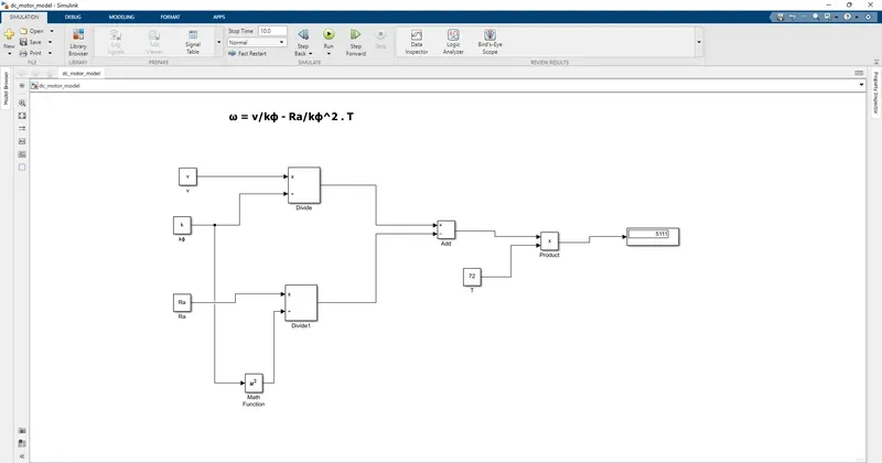
motor and controller parameters are taken from the above objective,
4. Referring to the block of the below link
https://www.tesla.com/blog/induction-versus-dc-brushless-motors
this link shows the Induction versus DC brushless motor by wally Rippel, tesla
Introduction:
wally Rippel is a long-time proponent of electric vehicles. He helped to develop the EV1 for general motors and he worked for the jet propulsion laboratory on electric vehicle battery research.
Evaluation of vehicle components :
According to wally rippel, there are different types of engines to suit personal requirements, such as price and performance. This is also true for electric vehicle drives.
In older days lead acid batteries, DC brush motors, and contactor controllers. But nowadays lead is replaced by lithium, DC brush motor is replaced by brushless DC motors, and contactors will be giving way to modulating inverters.
so, both induction and brushless machines "duke it out" for many years to come. Each will have its loyal proponents and religious detractors.
brushless DC motor:
According to the welly Rippel the brushless machine, The rotor includes two or more permanent magnets that generate a DC magnetic field (as seen from the vantage point of the rotor).in turn, this magnetic field enters the stator core(a core made up of him, stacked laminations) and interacts with the current flowing within the windings to produce a torque interaction between the rotor and stator. As the rotor rotates, the magnitude and polarity of the stator currents must be continuously
Maintaining torque and conversion of electrical to mechanical energy is optimally efficient. with these willy rippel says the device that provides the control is called an inverter. without it, brushless motors are useless motors.
Induction motor drives:
3-phase induction motors was invented by Nikola tesla sometime before 1889.curiously, the stators for 3-phase induction motors and the DC brushless motor are virtually indentical.Both have three sets of "distributed windings" that are inserted within the stator core. the essential difference between the two machines is with rotor.
Different like the DC brushless rotor, the induction rotor has no magnets _ just stacked steel laminations with buried pheripheral conductors that form a "shorted structure".
while
while 3-phase induction motors have great utility, they also have some severe limitations.They cannot operate from DC; AC is a must. shaft speed is proportionate to line frequency .hence, when used with utility power,they are constant speed machines.Finally when operated from utility power, they have limited starting torque and somewhat limited running peak torque capabilities, when compared to DC type machines.
As per author willy prepective:
Back in the 1990s all of the electric vehicle expect one were powered by DC brushless drives. Today, all the hybrids are powered by DC brushless drives, with no expections. The only notable uses of induction drives have been the general Motors EV-1; The AC propulsion vehicles, including the tzero;and the tesla roadster.
Both DC brushless and induction drives use motors having similar stators. Both drives use 3-phase modulating inverters. The only differences are the rotors and the inverter control code. (DC brushless drives require an absolute position sensor, while induction drives require only a speed sensor; these differences are relatively small.
One of the main differences is that much less rotor heat is generated with the DC brushless drive. Rotor cooling is easier and peak point efficiency is generally higher for this drive. The DC brushless drive can also operate at a unity power factor for the induction drive is about 85 percent. This means that the peak point energy efficiency for a DC brushless drive will typically be a few percentage points higher than for an induction drive.
In an ideal brushless drive, the strength of the magnetic field produced by the permanent magnets would be adjustable. When maximum torque is required, especially at low speeds, the magnetic field strength (B) should be maximum. So that inverter and motor currents are maintained at their lowest possible values. This minimizes the I 2 R (current^2 resistance losses and thereby optimizes effiency. Likewise, when torque levels are low, the B field should be reduced such that Eddy and hysteresis losses due to B are also reduced. Ideally, B should be adjusted such that the sum of the eddy, hysteresis, and i^2 is minimized. Unfortunately, there is no easy way of changing B with permanent magnets
CONCLUSION:
The author's conclusion is that DC brushless drives will like to dominate in the Hybrid and PHEV markets. Induction drives will maintain the dominance of the high-performance pure electrics.
welly Rippel's point of view is what will happen hybrids become pure electrical and as their performance will increase. The fact that so much of the hardware is common for both drives could mean that we will see induction and DC brushless life and work side by side during the coming golden era of hybrid and electric vehicles