Week-7 Challenge: DC Motor Control
1. A. Explain a MATLAB demo model named ‘Speed control of a DC motor using BJT H-bridge’.
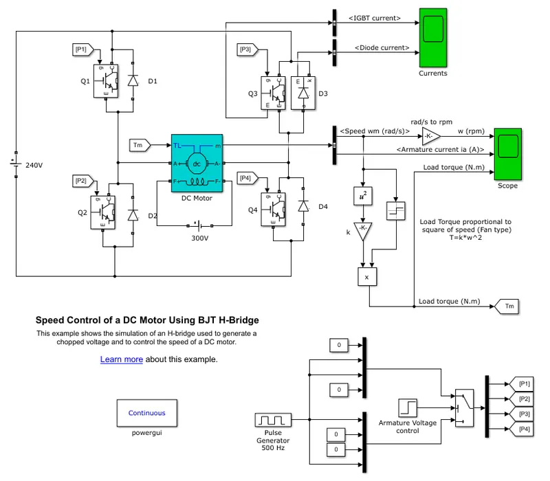
Here i have attached Simulink Model Snap of Speed control of a DC motor using BJT H-bridge.
Dc Motor Configuration is 5 HP 240V 1750 rpm. 240V source is connected into H-Bridge BJT(Bi-Polar Junction Transistro).
Q1,Q2,Q3,Q4 is Named BJT Circuits.D1,D2,D3,D4 is Named Diodes.The Bipolar Junction Transistor (BJT) when used for power switching applications, operates as an IGBT.
When it is conducting (BJT operating in the saturated region), a forward voltage Vf is developed between collector and emitter (in the range of 1 V).
Therefore, the IGBT block can be used to model the BJT device. he H-bridge consists of four BJT/Diode pairs (BJT simulated by IGBT models).
Two transistors are switched simultaneously: Q1 and Q4 or Q2 and Q3. When Q1 and Q4 are fired, a positive voltage is applied to the motor and diodes D2-D3
operate as free-wheeling diodes when Q1 and Q4 are switched off. When Q2 and Q3 are fired, a negative voltage is applied to the motor and diodes D1-D4
operate as free-wheeling diodes when Q2 and Q3 are switched off. it simulates a fan type load (where Load torque is proportional to square of speed)(T=k*W^2).
Scope results of IGBT Current and Diode Current have attached in Q3 Diodes. Pulse Generator duty cycle is 75% and Peroid time is 0.002 sec and Amplitude is 1. We are given 0 is Switching on Condition and 1 is off Condition and Four pulse Generator signals are fed MuxBlock and compile into One signal switch based three way switching condition and Threshold Value. With help of switch DemuxBlock divide into four signal for four IGBT Circuits.
Total simulatio time is 1 Sec, Armature Voltage Control Threshold is 0.5 and 0.5Ra is applied into P1,P2,P3,P4 For each intervals.
Motor speed is Rad/sec is Connected into Rpm with using gain block (30/PI), and armature current and Load torque is connected in scope.
B. Comment on the armature current shoot-up from the scope results.
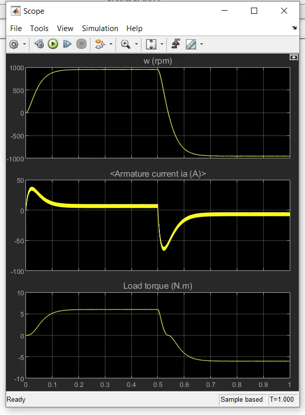
The motor starts in the positive direction with a duty cycle of 75% (mean DC voltage of 180V(240*0.75)). At t= 0.5 sec.,
the armature voltage is suddenly reversed and the motor runs in the negative direction.
C. Refer to the help section of ‘The Four-Quadrant Chopper DC Drive (DC7) block’. Compare it with the H-bridge model.
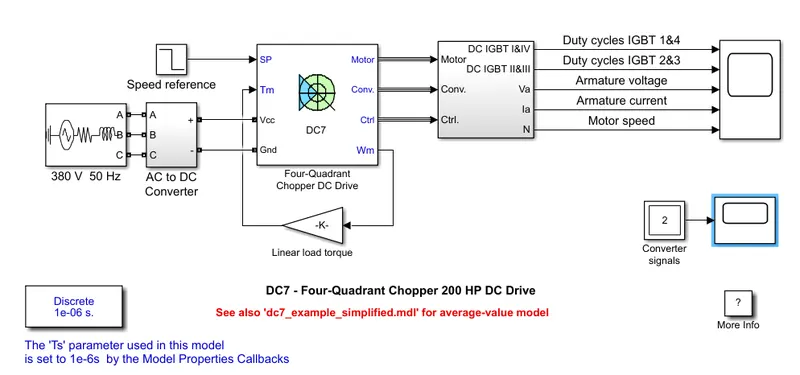
Four Quarant Of Chopper Block:
H-bridge model.
H-Bridge Circuit:
In H-bridge circuit have four IGBT ciruit have connected in Series path. The dc Motor is motor is connected in middle of H-bridge.
Based on oppposite switching action motor amature voltage has been contorlled. The difference of H-bridge circuit and chopper circuit is The Quarant operattion
In H-Bridge is Controlled Two Quarant opeation and terminal voltage is connected to motor terminal together the motor will brake or stop.
Advantages:
1. 1. Very high efficiency.
2. Very low loss.
3. This circuit can be placed in small places.
Four-Quadrant Chopper DC Drive (DC7) block:
The Four-Quarant chopper dc drive(DC7) block have GTO, IGBT, MOSFET, Thyristor and averged Switch is available, Based on requirement we switching the switches.
DC-DC chopper have used in step up and step down the dc voltage using the semi-conductor switches. The four Quadrant Operation is Forward Motoring(T+, W+) and Reverse Braking(T-, W+)
Regenrative Braking(T+,W-), Reverse Motoring(T-,W-). Here T is Torque and W is Speed. Based on Input Voltage control the load volatage has been controlled.
Advantages:
1. It is used in battery-operated vehicles for fast dynamic response.
2. It is used for control of a.c. series motors in traction systems.
3. It is used for control of a large number of d.c. motors.
4. It can be used to control the speed of (wound rotor) induction motor
2. Develop a 2-quadrant chopper using simulink & explain the working of the same with the relevant results. (Refer to article - Multiquadrant operation of motor )
Here i have attached 2-quarant chooper model using simulink, pulse generator produce pulse and duty cycle value also 75%
assign input signal into two igbt swithces and didoes, dc violtage source have attached to given input voltage of two semiconductor switches, dc machine have attched and scope also attached in dc motor. power gui is used.
3. Explain in a brief about operation of BLDC motor.
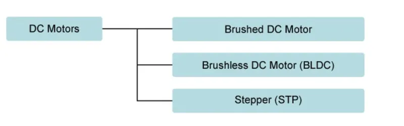
BLDC is called brushless Dc Motor it is part of dc Motor and here i have mentioned dc motor Types:
Brushless Dc Motor:
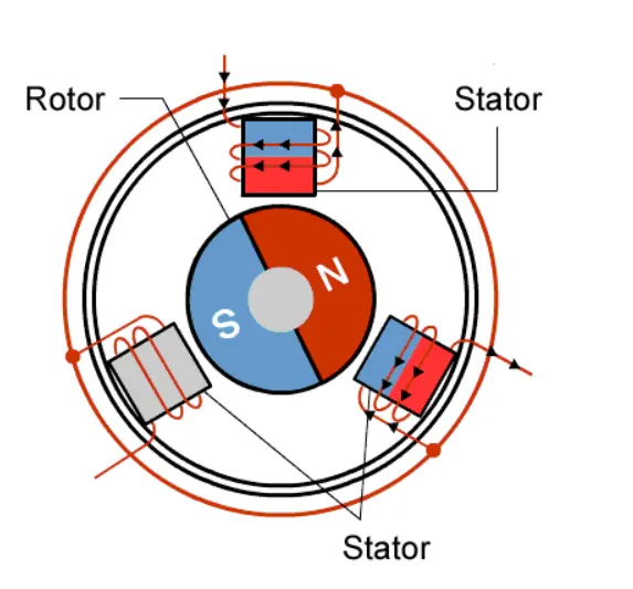
Brushless Dc Motor Working Principle:
In brushless DC motors do not use brushes. With brushed motors, the brushes deliver current through the commutator into the coils on the rotor.
In BLdc the rotor is a permanent magnet and the coils do not rotate, but used in fixed stator.the permanent magnet that rotates and rotation is achieved by changing the direction
of the magnetic fields generated by the surrounding stationary coils. To control the rotation, you adjust the magnitude and direction of the current into these coils.
So the rotor is a permanent magnet, it needs no current, eliminating the need for brushes and commutator. Current to the fixed coils is controlled from the outside.
A BLDC motor with three coils on the stator will have six electrical wires (two to each coil) extending from these coils.
In most implementations three of these wires will be connected internally, with the three remaining wires extending from the motor body.
Advantages of BLDC Motors:
1. High efficiency
2. In BLDC Can control continuously at maximum rotational force (torque)
3. In BLDC motors can be controlled, using feedback mechanisms and to delivery precisely the desired torque and rotation speed
4. In BLDC motors also offer high durability and low electric noise generation
5. BLDC have a long operating life
6. BLDC motors are better suited to controlling the force.
7. BLDC motors can also deliver more precise control in which turn can further extend battery life.
Applications for BLDC Motors:
1. Washing machines, air conditioners, and other consumer electronics
2. Vacuum machines
3. drones