Week-7 Challenge: DC Motor Control
1. A. Explain a MATLAB demo model named ‘Speed control of a DC motor using BJT H-bridge’.
B. Comment on the armature current shoot-up from the scope results.
C. Refer to the help section of ‘The Four-Quadrant Chopper DC Drive (DC7) block’. Compare it with the H-bridge model.
ANSWER:
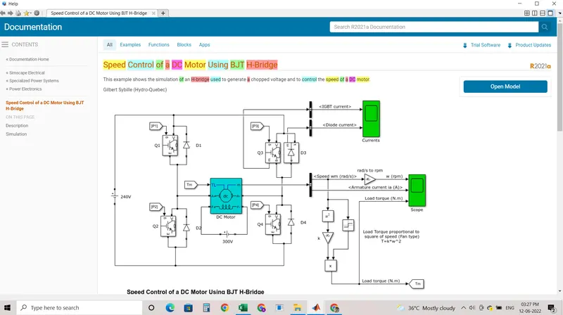
Working of H-bridge model:
• Here H-bridge DC chopper circuit is designed to control the speed of the motor.
• IGBT acts as BJT in power switching devices.
• Four IGBT switches are used for inverting the DC voltage 0 to 240 v supply. The current flows from collector(C) to emitter (E).
• The gate are controlled by the pulses (0 and 1) according to the armature voltge of motor given by pulse generator.
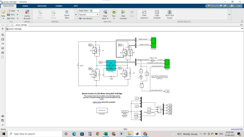
• This image shoes the voltage value given from initial to final during the step time.According to the pulses on and off the voltage supplied to the IGBT's.
• Here four switches are used Q1,Q2,Q3,Q4. Pulses P1,P2,P3,P4 are conected with corresponding switches.
• In first state, Q1 and Q4 are closed by giving IV to IGBT'S,current from battery passes through Q1 and Q4.Diode D2,D3 are used as free wheeling diode in this state.In this case Forward motoring and forward breaking are held.
• In Second state,Q2 and Q3 are closed by giving IV to IGBT's,current from battery passes through Q2 and Q3.Diode DI,D4 are used as free wheeling diode in this stateln this case reverse motoring and reverse breaking are held.The current direction change its direction in this state.
• Both the states are occuring in 0.5 seconds in their sample time.Thus DC supply converted and feeded to the armature of the motor.
• Here free wheeling diodes are used as a safety purpose of this inverter circuit as when the flow of current on low values protects the circuit and machine by feed backing the current or in high voltage fluctuvations voltage get splited as protection to the motor and circuit components.
• In motor operation, armature terminals are connected with a 240V along the inverter circuit and field windings are connected with 300 V DC suppy to act as a electro magnet for the motor.
The load torque is given as mechanical input to the motor for its referance.
• Thus through this magnetic fields generated, variable current carring conductors in rotor armature produces forces according to fleming left hand rule principle. Thus the motor starts to rotate.
• Here run this demo model and study the results from scopes.
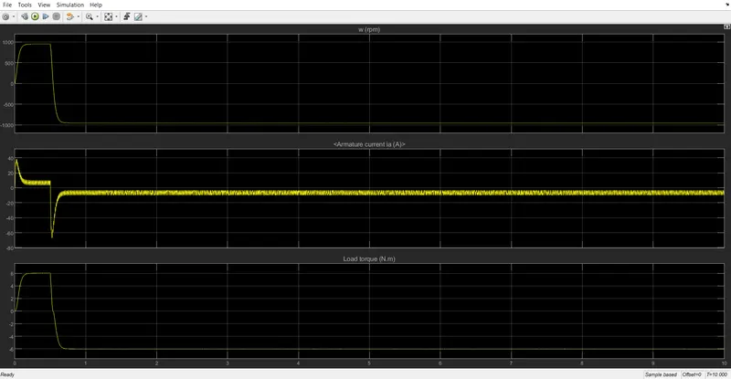
From the result scope we are getting,
Speed of motor:
Initially increases to 0 to nearly 900 rpm upto 0.5 secs (Forward motoring action takes place • Then speed reduces to 0 rpm (Forward dynamic breaking action takes place).
• Then speed increases from 0 to -900 rpm at upto 1 sec (Reverse motoring action takes plac • Then reverse dynasmic breaking occurs (Not shown in scope).
Load torque of motor:
Initially torque increase from 0 to 0.5 secs in forward motoring action.
• Then torque reduces to 0 Nm in forward dynamic breaking mode.
• Then torque increases in reverse direction in reverse motoring action upto 1 sec.
• Again torque reduce to zero. (Not shown in scope).
3. Explain in a brief about operation of BLDC motor.
ANSWER:
Working Principle and Operation of BLDC Motor
BLDC motor works on the principle similar to that of a conventional DC motor, the Lorentz force law which states that whenever a current carrying conductor placed in a magnetic field it experiences a force. As a consequence of reaction force, the magnet will experience an equal and opposite force. In case BLDC motor, the current carrying conductor is stationary while the permanent magnet moves.
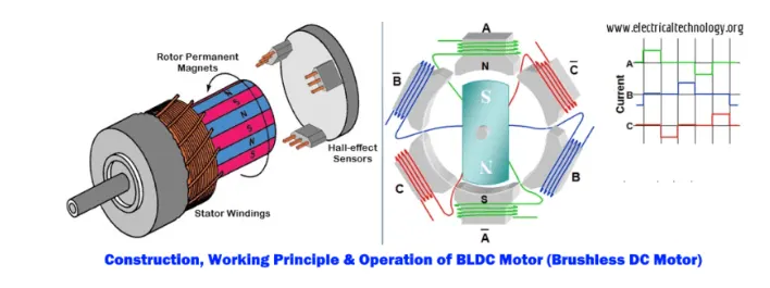
When the stator coils are electrically switched by a supply source, it becomes electromagnet and starts producing the uniform field in the air gap. Though the source of supply is DC, switching makes to generate an AC voltage waveform with trapezoidal shape. Due to the force of interaction between electromagnet stator and permanent magnet rotor, the rotor continues to rotate.
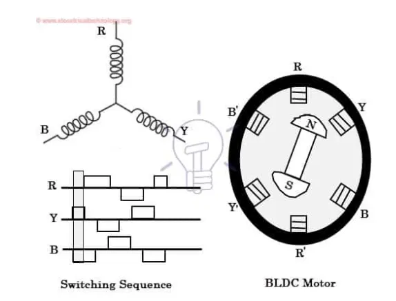
Consider the figure below in which motor stator is excited based on different switching states. With the switching of windings as High and Low signals, corresponding winding energized as North and South poles. The permanent magnet rotor with North and South poles align with stator poles causing motor to rotate.
Observe that motor produces torque because of the development of attraction forces (when North-South or South-North alignment) and repulsion forces (when North-North or South-South alignment). By this way motor moves in a clockwise direction.
Advantages of BLDC Motor
- t has no mechanical commutator and associated problems
- High efficiency due to the use of permanent magnet rotor
- High speed of operation even in loaded and unloaded conditions due to the absence of brushes that limits the speed
- Smaller motor geometry and lighter in weight than both brushed type DC and induction AC motors
- Long life as no inspection and maintenance is required for commutator system
- Higher dynamic response due to low inertia and carrying windings in the stator
- Less electromagnetic interference
Disadvantages of Brushless Motor
- These motors are costly
- Electronic controller required control this motor is expensive
- Not much availability of many integrated electronic control solutions, especially for tiny BLDC motors
- Requires complex drive circuitry
- Need of additional sensors
- Quite operation (or low noise) due to absence of brushes.
2. Develop a 2-quadrant chopper using simulink & explain the working of the same with the relevant results. (Refer to article - Multiquadrant operation of motor )
ANSWER:
Type C chopper is obtained by connecting type –A and type –B choppers in parallel. We will always get a positive output voltage V0 as the freewheeling diode FD is present across the load. When the chopper is on the freewheeling diode starts conducting and the output voltage v0 will be equal to Vs . The direction of the load current i0 will be reversed. The current i0 will be flowing towards the source and it will be positive regardless the chopper is on or the FD conducts. The load current will be negative if the chopper is or the diode D2 conducts. We can say the chopper and FD operate together as type-A chopper in first quadrant. In the second quadrant, the chopper and D2 will operate together as type –B chopper.
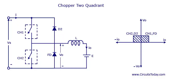
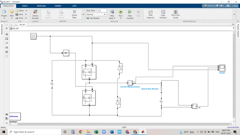
CIRCUIT DIAGRAM FOR TWO QUADRANT CHOPPER:
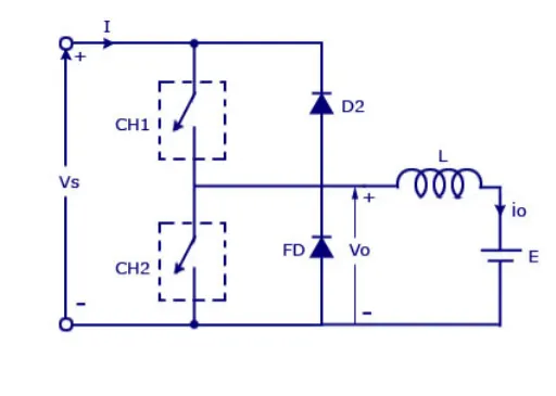
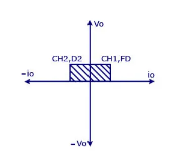
two quadrant chopper is also called as type c chopper. Type C chopper is obtained by connecting type –A and type –B choppers in parallel. We will always get a positive output voltage V0 as the freewheeling diode FD is present across the load. When the chopper is on the freewheeling diode starts conducting and the output voltage v0 will be equal to Vs . The direction of the load current i0 will be reversed. The current i0 will be flowing towards the source and it will be positive regardless the chopper is on or the FD conducts. The load current will be negative if the chopper is or the diode D2 conducts. We can say the chopper and FD operate together as type-A chopper in first quadrant. In the second quadrant, the chopper and D2 will operate together as type –B chopper.
The average voltage will be always positive but the average load current might be positive or negative. The power flow may be life the first quadrant operation ie from source to load or from load to source like the second quadrant operation. The two choppers should not be turned on simultaneously as the combined action my cause a short circuit in supply lines. For regenerative braking and motoring these type of chopper configuration is used.
MAKING MODEL;
let us take two mosfet blocks and diodes blocks and connect it as shown in circuit diagram.
the dc voltage source is connected as shown.
let the voltage of dc voltage source be 24 volts.
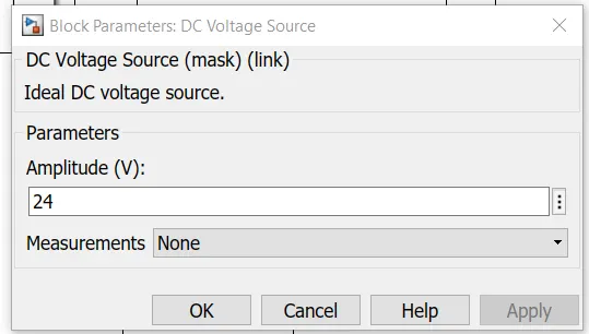
let us consider an series RLC branch block and select inductor L . thus block works as a load.
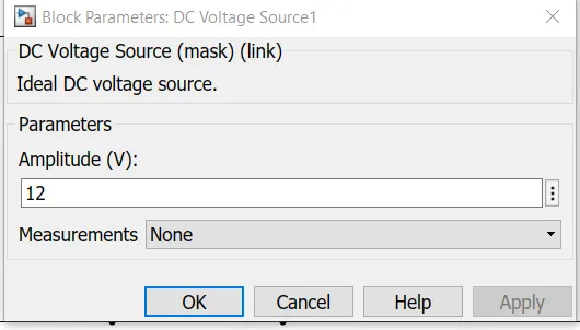
to consider LE load ie motor load , and dc voltage source of 12 volt is also connected in series with inductor.
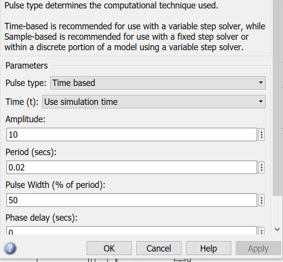
The pulse generator block is used to create gate pulse.
the not gate is used in the model so that the two mosfet will not get closed at the same time otherwise short circuit will occur .due to use of not gate , when one mosfet is ON the other mosfet will get off and when other mosfet is ON the first mosfet will get off .
The amplitude of pulse generator is kept 10 so that we can clearly see the pulses at scope and let period be 0.02 seconds and let pulse weidth be 50%
TWO QUADRANT CHOPPER MODEL USING SIMULINK:
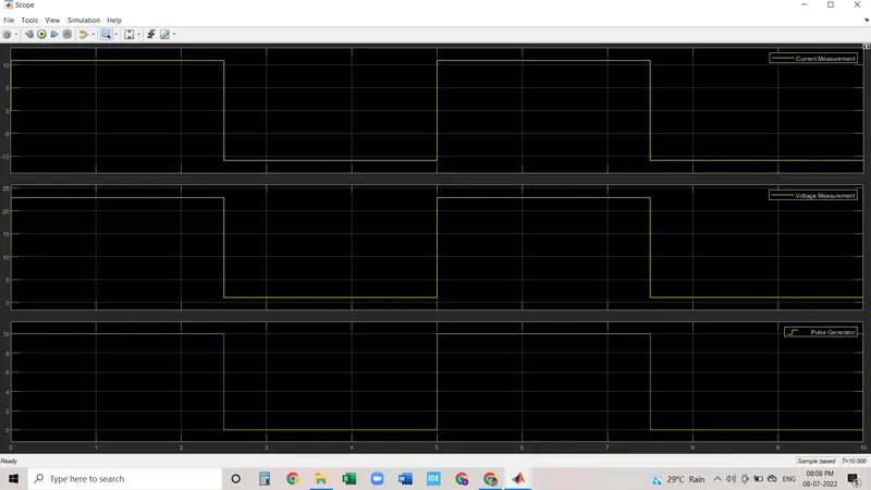
RESULT :