Week-7 Challenge: DC Motor Control
1. A.
Explain a MATLAB demo model named ‘Speed control of a DC motor using BJT H-bridge ?
Fast off all ,let us understand the basic concept of speed control using H bridge congfiguration .
Most DC motor have two terminals because they are series type (armature and field windings are connected in series )DC motor.
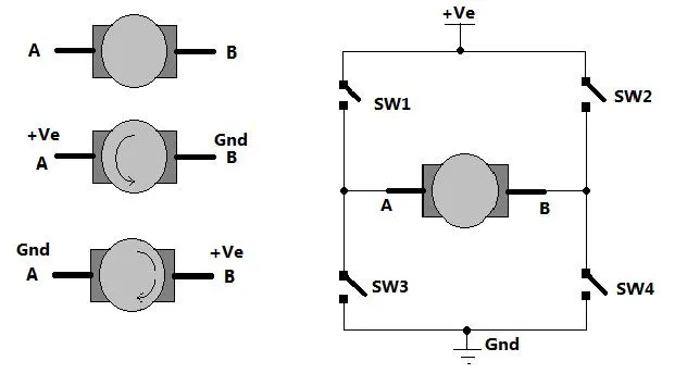 An H-Bridge is a circuit of 4 switches allowing to select the direction of current flowing through a part. The simplest H-Bridge consists of four manually controlled switches. The name is derived from the circuit diagram which looks like a capital H.The H-bridge is an electronic circuit that looks like the letter H. An H-bridge is used to drive a load, such as a brushed DC motor, in both directions. And it controls the flow of current to a load. As shown in figure there are two terminals'A'and 'B' of DC motor.Now if we connect terminal A with +Ve supply and B with -Ve supply or ground ground the current will flow from motor from A to B and motor will rotate in one direction say clockwise or forward direction .now B is connected with +Ve and A is connected to ground .THe current will flow from motor from B to A and motor will rotate in other direction . The arrangement to get reversible supply is shown in right side of figure .Four switches are connected in between +Ve supply and ground and DC motor is connected in btw two switch as shown .such circuit arrangement is known as H-bridge .if SW1 and SW4 are pressed simultaneously then current will flow from +Ve - SW1 - A-B-SW4 -Gnd.so motor will rotate in one direction .open SW! and SW$ to stop motor.Now if SW2 and SW3 are pressed current will flow from another Direction .
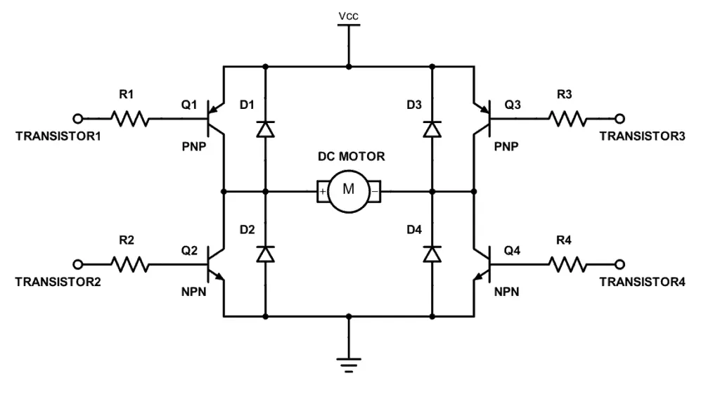 The circuit replace switch with NPN type transistor.diode are given for the current to free wheel as the DC motor is a RLE load where the current cannot change direction .instantaneously.We all know that transistor if will turn on and if we give ) input it will be turn off(cut off region),so in this circuit is Q1 and Q4 are turned ON simultaneously the motor will rotate in reverse direction.
In order to very the speed of the DC motor we have to change the voltage applied to the de motor .this could be achived with the help of pulse width modulation.
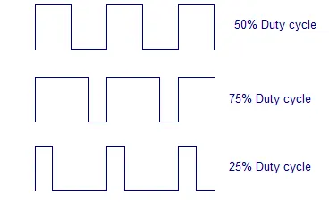 pulse width modulation means varying the width of pulse .width means on time Ton of pulse .The average output voltage (Vdc or Vavg )is given by equation Vdc =Ton/Ton + Toff .Vs The example below shows the simulink model of an H-bridge used to generate a choppeed voltage and to control the speed of a DC motor.
The bipolar Junction Transistor(BJT) when used for power switching applications.operaters as an IGBT .when it is conducting a forword voltage Vf is develop between collector and emmiter .therefore the IGBT block can be used to model the BJT device.
The H-bridge consists of four BJT/Diode pairs .Two transistor are switched simultaneously :Q1 and Q4 or Q2 and Q3.when Q1 and Q4 are fired ,a positive voltage is applied to the motor and diodes D2-D3 opperates as free wheeling diods when Q1 and Q4 are switch off .when Q2 and Q3 are fired a nagative voltage is applied to the motoor and Diodes D1 and D4 opperates as free wheeling diode when Q2 and Q3 are switched off.
B. Comment on the armature current shoot-up from the scope result . Simulation Output :
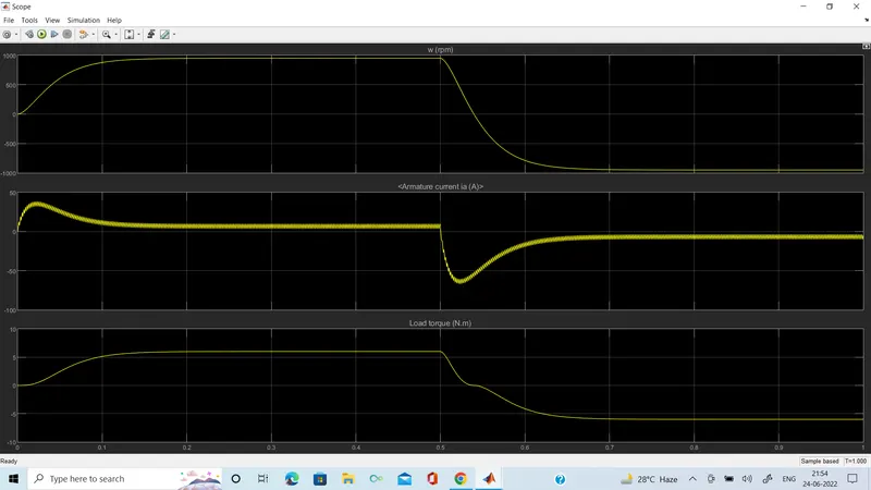 initially,there is a spike in armature current .This is because ,in a DC motor,
Ia = (V - Eb )/Ra
Where
Ia –mis the armature current
v- is the supply voltage
Eb- back emf and
Ra-armature resistance
At starting ,Eb=0 as speed=0 at starting.
Therefore, Ia=V/Ra Ia=V/Ra
And Ra is a very small value ,Hence Ia is huge and that reflects in the graph .
2.
Period :2 milli seconds Pulse Width (% of period ):50%
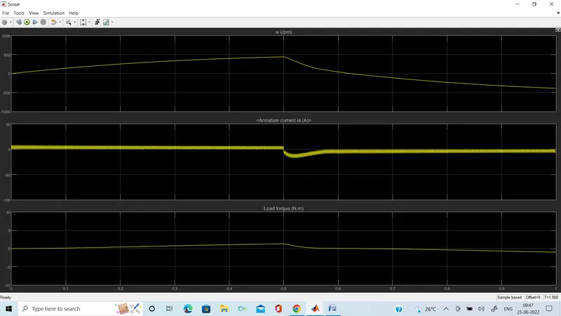 Therefore when pulse Width is decreases ,the voltage applied across the DC motor and the armature current finally decreases.
1.C. Refer to the help section of ‘The Four-Quadrant Chopper DC Drive (DC7) block’. Compare it with the H-bridge model :
The Four Quadrant Chopper DC drive (DC7) block represents a four quadrent chopper drive for DC motor .This drive feature close loop speed control with the four quadrent opetraction . the speed contriol loop outputs the reference armature current of the machine using a PI current controller ,the chopper Duty cycle corresponding to the commanded armature current is derived .The duty cycle is than compare with a sawtooth carrier signal to obtain the required PWM signal to the chopper .
For model these blocks from the Electric fundamental drives block library :
- Speed controller (DC)
- Regulation Switch
- Current Controller (DC)
- Chopper
H bridge
Four Quadrant chopper DC drive
Only Two quadrant of operaction are possible .They are Forword motoring and reverse motoring
It can operate in all four quadrants ,the high armature current ripple .Lower armature current ripple due to High switching frequency of DC-DC coverters . This widely used in Automobile .
2.Develop a 2-quadrant chopper using simulink & explain the working of the same with the relevant results. (Refer to article - Multiquadrant operation of motor )
Type C chopper or Two Quadrant class A chopper :
class -C or Type -C chopper is a catagory of chopper which can operate in the first as well as second quadrant .this basically means that the power can either flow from source to load or load to source in this chopper .this kind of chopper is also known as Two quadrant Class-A chopper.
working of Class-C or type C :
As we know that a class A and class B chopper operates in first and second quadrant respectively .therefore if we connect both this type of chopper in paralle then it is possible to have chopper operaction in first as well as second quadrent .In fact class_C or Type chopper isobtained by the paralle connection of class A and class B chopper .
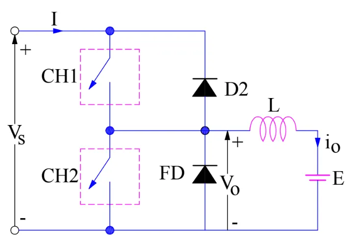
case 1: When CH1 is switched ON/OFF
when Chopper CH1 is switch ON ,source Vs directly gets connected to the load and hence ,load voltage V0 is equal to source voltage .The direction of load current is from source to load as shown in the circuit diagram which is assumed positive .
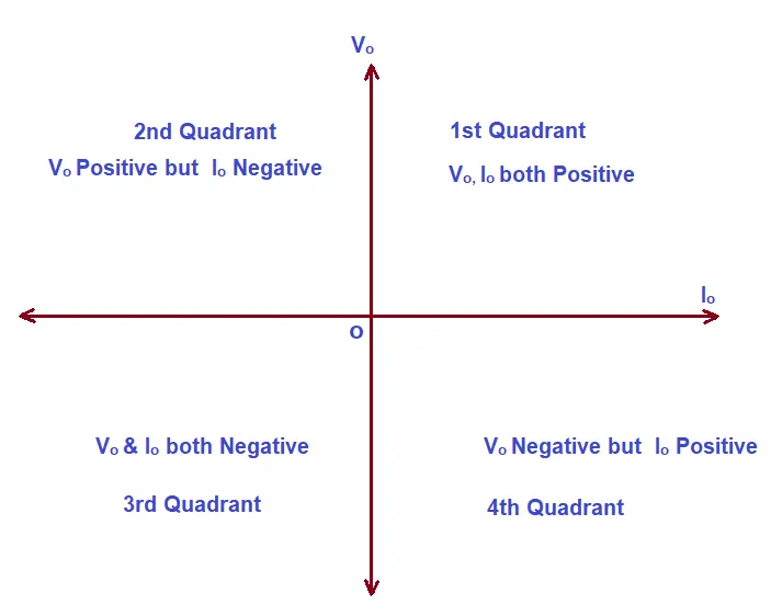
When CH1 is switch off ,the free wheeling diode FD comes into the circuit as it gates forword biased and hence shorts the load .therefore the output voltage V0 become Zoro.However the i0 continous to die down through the FD and L in the same direction as shown the circuit diagram .thus the average output voltage V0 and current I0 are positive and hence operation of chopper is in first quadrant.
Case 2: When CH2 is switched ON/OFF
When Chopper CH2 is switched on the load DC source E drives current through CH2 and load .The direction of this current I0 will be opposite to that shown in the circuit diagram and hence is assumed nagative .output voltage V0 is 0 during this timee. when CH2 is mode off diode D2 gets forward biased and hence the current into the source from the load . The avarage load voltage always positive but the average load current may be positive or negative .therefore the power flow may be from source to load (1st quadrant)or load to source (2nd quadrant )The operation region of Class_C chopper is shown below by hatched area.
3.
Explain in a brief about operation of BLDC motor:
Here we know all about of BLDC motor ,why it called Brushless and what is different between brushed and brushless motor.
Main focus on BLDC motor : Brushless DC motors (BLDC) have been a much focused area for numerous motor manufacturers as these motors are increasingly the preferred choice in many applications, especially in the field of motor control technology. BLDC motors are superior to brushed DC motors in many ways, such as ability to operate at high speeds, high efficiency, and better heat dissipation.They are an indispensable part of modern drive technology, most commonly employed for actuating drives, machine tools, electric propulsion, robotics, computer peripherals and also for electrical power generation. With the development of sensorless technology besides digital control, these motors become so effective in terms of total system cost, size and reliability.
What is BLDC motor ? A brushless DC motor (known as BLDC) is a permanent magnet synchronous electric motor which is driven by direct current (DC) electricity and it accomplishes electronically controlled commutation system (commutation is the process of producing rotational torque in the motor by changing phase currents through it at appropriate times) instead of a mechanically commutation system. BLDC motors are also referred as trapezoidal permanent magnet motors. Difference between brushed and brushedless DC motor : Motor is an electrical machine that converts electrical energy into mechanical energy. It takes electrical current as its input and it starts rotating to drive some mechanical load. The advancement in motor technologies allows the use of DC motors in various applications from small toys to cordless power tools and conveyor belts in industries. There are two major types of DC motors i.e. brushed and brushless motor and choosing the best one for a specific application is very necessary. Visually these both may look the same and are operated from the same source but their operation and performance is quite different.
In this article, we are going to enlist the differences between brushed and brushless motor. But first, let’s discuss their basics and how they work.
The brushed motors are the earliest motor in the history. It uses carbon brushes mechanism to supply power to the rotating part of the machine called rotor. While the stator which is made of permanent magnet surrounds the rotor.
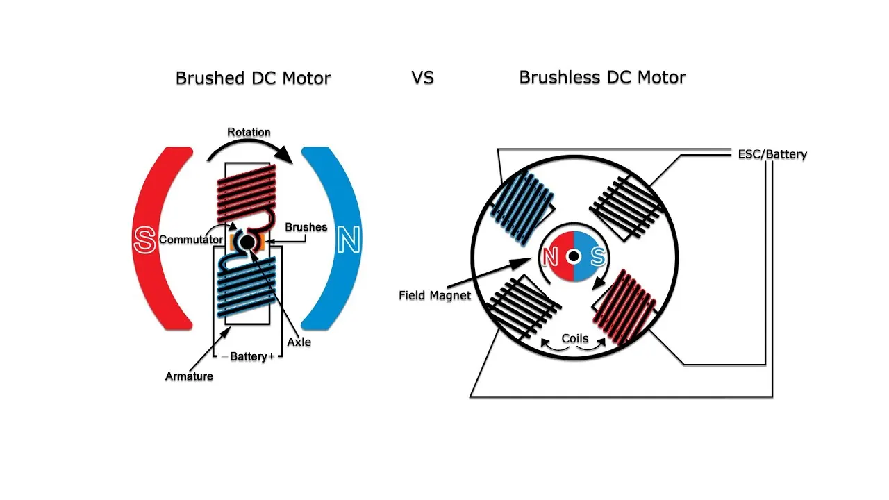 The rotor has armature windings and slip rings as well as an external shaft to drive load. The windings carry the input current which is supplied through the slip ring commutator that connects the stationary circuit and rotating armature windings while also changes the supplied DC current after each half cycle to allows continuous spinning of rotor.
Since the current carrying windings are placed inside a magnetic field generated by the permanent magnet of the stator, the rotor experiences a rotational force. When the rotor rotates, the brushes slide across the slip ring which decreases its life-span due to the friction.
The BLDC motor as its name suggests, does not have brushes and it does not require it to operate. It is designed for the sole purpose of the removing the brushes from the previousSince there are no brushes, the input power is supplied to the stator of the motor which in this case is made of multiple windings that surrounds the rotor. While the rotor is made of permanent magnet.
The input is switched between the stators windings to generate magnetic field that push and pull on the rotor’s magnetic field causing it rotate in its direction. A hall effect sensor is used to detect the position of the rotor and switch the input to the correct stators winding respectively.
Since the DC input to the stator needs to be switched, such motors used electronic commutations instead of mechanical commutation using switching devices such as thyristors. These switches are controlled using microcontroller to precisely switch the input between the stators windings. It essentially switches the DC input into a 3-phase supply which generates a smooth rotating magnetic field.
The controller used for brushless motor is more sophisticated and very expensive. It does no operate without its controller which also offers the precise speed control and positioning of the rotor. But the cost of the controller is far more greater then the motor itself.
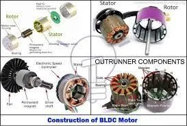
Construction of BLDC Motor
BLDC motors can be constructed in different physical configurations. Depending on the stator windings, these can be configured as single-phase, two-phase, or three-phase motors. However, three-phase BLDC motors with permanent magnet rotor are most commonly used.
The construction of this motor has many similarities of three phase induction motor as well as conventional DC motor. This motor has stator and rotor parts as like all other motors.Stator of a BLDC motor made up of stacked steel laminations to carry the windings. These windings are placed in slots which are axially cut along the inner periphery of the stator. These windings can be arranged in either star or delta. However, most BLDC motors have three phase star connected stator.Each winding is constructed with numerous interconnected coils, where one or more coils are placed in each slot. In order to form an even number of poles, each of these windings is distributed over the stator periphery.
Working Principle and Operation of BLDC Motor
BLDC motor works on the principle similar to that of a conventional DC motor, i.e., the Lorentz force law which states that whenever a current carrying conductor placed in a magnetic field it experiences a force. As a consequence of reaction force, the magnet will experience an equal and opposite force. In case BLDC motor, the current carrying conductor is stationary while the permanent magnet moves.
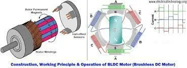
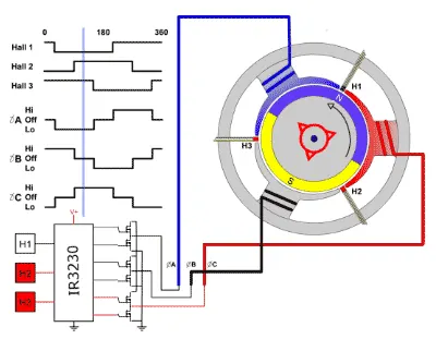
When the stator coils are electrically switched by a supply source, it becomes electromagnet and starts producing the uniform field in the air gap. Though the source of supply is DC, switching makes to generate an AC voltage waveform with trapezoidal shape. Due to the force of interaction between electromagnet stator and permanent magnet rotor, the rotor continues to rotate. in which motor stator is excited based on different switching states. With the switching of windings as High and Low signals, corresponding winding energized as North and South poles. The permanent magnet rotor with North and South poles align with stator poles causing motor to rotate.Observe that motor produces torque because of the development of attraction forces (when North-South or South-North alignment) and repulsion forces (when North-North or South-South alignment). By this way motor moves in a clockwise direction. Here, one might get a question that how we know which stator coil should be energized and when to do. This is because; the motor continuous rotation depends on the switching sequence around the coils. As discussed above that Hall sensors give shaft position feedback to the electronic controller unit.Based on this signal from sensor, the controller decides particular coils to energize. Hall-effect sensors generate Low and High level signals whenever rotor poles pass near to it. These signals determine the position of the shaft.
Advantages of BLDC Motor
BLDC motor has several advantages over conventional DC motors and some of these are
- It has no mechanical commutator and associated problems
- High efficiency due to the use of permanent magnet rotor
- High speed of operation even in loaded and unloaded conditions due to the absence of brushes that limits the speed
- Smaller motor geometry and lighter in weight than both brushed type DC and induction AC motors
- Long life as no inspection and maintenance is required for commutator system.
Disadvantages of Brushless Motor
- These motors are costly
- Electronic controller required control this motor is expensive
Applications :
- Computer hard drives and DVD/CD players
- Electric vehicles, hybrid vehicles, and electric bicycles
- Industrial robots, CNC machine tools, and simple belt driven systems
- Washing machines, compressors and dryers
- Fans, pumps and blowers