Week-7 Challenge: DC Motor Control
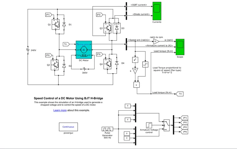
1. A. Explain a MATLAB demo model named ‘Speed control of a DC motor using BJT H-bridge’.
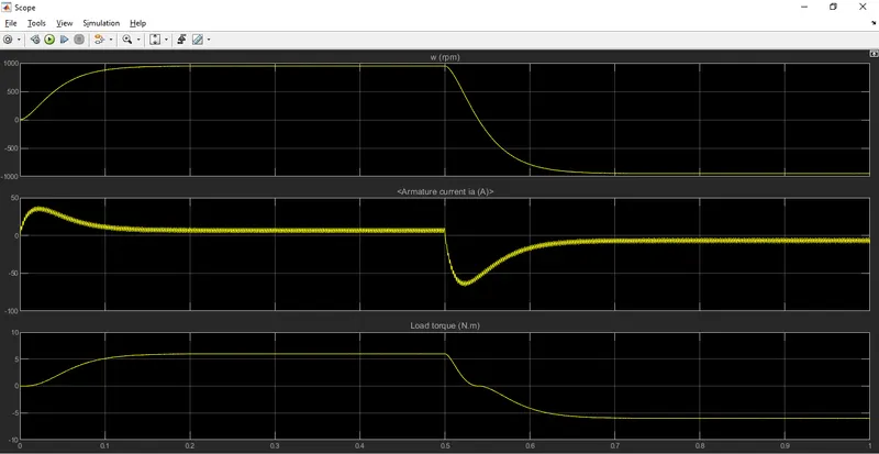
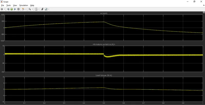
B. Comment on the armature current shoot-up from the scope results.
C. Refer to the help section of ‘The Four-Quadrant Chopper DC Drive (DC7) block’. Compare it with the H-bridge model.
Answer A:
BJT(Bipolar junction Transistor):
A bipolar junction transistor is a three-terminal semiconductor device that consists of two p-n junctions which are able to amplify or magnify a signal. It is a current controlled device. The three terminals of the BJT are the base, the collector, and the emitter
Speed control of a DC motor using BJT H bridge:
The Bipolar Junction Transistor (BJT) when used for power switching applications, operates as an IGBT. When it is conducting (BJT operating in the saturated region), a forward voltage Vf is developed between collector and emitter (in the range of 1 V). Therefore, the IGBT block can be used to model the BJT device.
The IGBT block does not simulate the gate current controlling the BJT or IGBT. The switch is controlled by a Simulink® signal (1/0). The DC motor uses the preset model (5 HP 24V 1750 rpm). It simulates a fan type load (where Load torque is proportional to square of speed). The armature mean voltage can be varied from 0 to 240 V when the duty cycle (specified in the Pulse Generator block) is varied from 0 to 100%.
The H-bridge consists of four BJT/Diode pairs (BJT simulated by IGBT models). Two transistors are switched simultaneously: Q1 and Q4 or Q2 and Q3. When Q1 and Q4 are fired, a positive voltage is applied to the motor and diodes D2-D3 operate as free-wheeling diodes when Q1 and Q4 are switched off. When Q2 and Q3 are fired, a negative voltage is applied to the motor and diodes D1-D4 operate as free-wheeling diodes when Q2 and Q3 are switched off.
Model:
Answer B:
Scope:
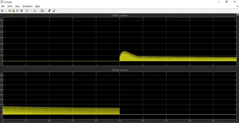
The motor starts in the positive direction with a duty cycle of 75% (mean DC voltage of 180V). At t= 0.5 sec., the armature voltage is suddenly reversed and the motor runs in the negative direction.
IGBT current and Diode Current:
Duty cycle value is 75%
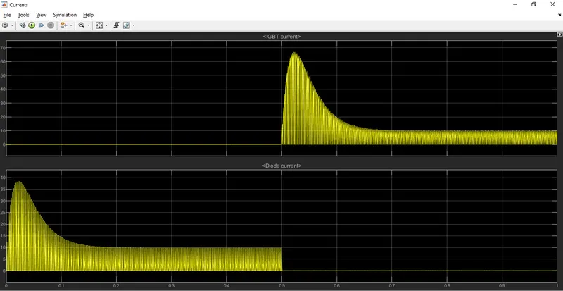
Duty Cycle value is 50%:
RPM ,Armature current and Load Torque:
Duty Cycle value is 75%
Duty Cycle value is 50%:
Answer C:
Four Quadrant Chopper DC Drive:
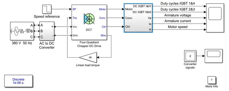
The 200 HP DC motor is separately excited with a constant 150 V DC field voltage source. The armature voltage is provided by an IGBT converter controlled by two PI regulators. The converter is fed by a 515 V DC bus obtained by rectification of a 380 V AC 50 Hz voltage source. In order to limit the DC bus voltage during dynamic braking mode, a braking chopper has been added between the diode rectifier and the DC7 block.
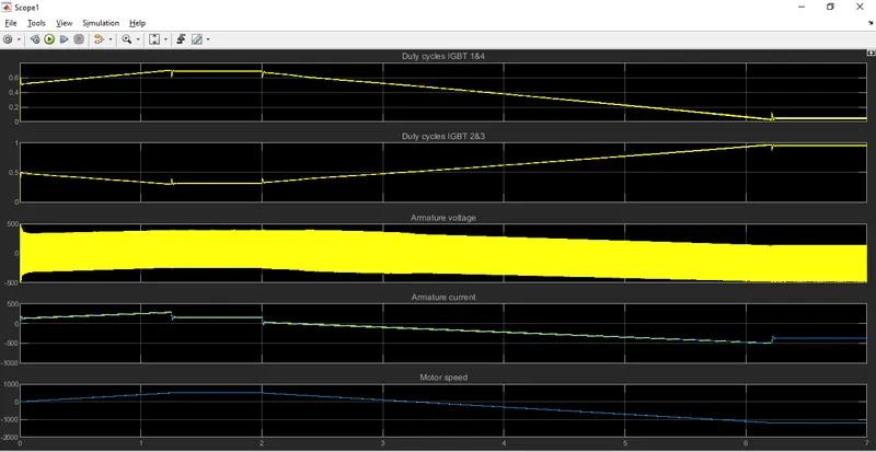
The first regulator is a speed regulator, followed by a current regulator. The speed regulator outputs the armature current reference (in p.u.) used by the current controller in order to obtain the electromagnetic torque needed to reach the desired speed. The speed reference change rate follows acceleration and deceleration ramps in order to avoid sudden reference changes that could cause armature over-current and destabilize the system. The current regulator controls the armature current by computing the appropriate duty ratios of the 5 kHz pulses of the four IGBT devices (Pulse Width Modulation). For proper system behaviour, the instantaneous pulse values of IGBT devices 1 and 4 are opposite to those of IGBT devices 2 and 3. This generates the average armature voltage needed to obtain the desired armature current. In order to limit the amplitude of the current oscillations, a smoothing inductance is placed in series with the armature circuit.
Difference between four Quadrant chopper DC drive and H bridge :
Four Quadrant Chopper DC drive:
- The direction of the motor can be changed by changing the polarity..
- It has border torque and power output ranges..
- upto 400 v can be achieved..
- The current has chopped values and the regenerative braking is possble..
H-bridge:
- The direction of the motor can be changed by changing the current signal by interupted .
- It uses single pulse generator which gives narrow torque and power output range ..
- Upto 350v can be achieved ..
- The current has continous values and the regenerative braking is not possible..
Output:
2. Develop a 2-quadrant chopper using simulink & explain the working of the same with the relevant results. (Refer to article - Multiquadrant operation of motor )
Answer:
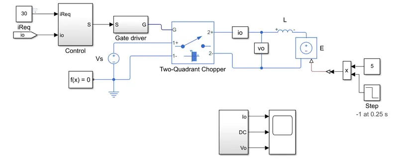
The Two-Quadrant Chopper block represents a two-quadrant controlled chopper for converting a fixed DC input to a variable DC output. The block contains two switching devices. Options for the type of switching devices are:
-
GTO — Gate turn-off thyristor. For information about the I-V characteristic of the device, see GTO.
-
Ideal semiconductor switch — For information about the I-V characteristic of the device, see Ideal Semiconductor Switch.
-
IGBT — Insulated-gate bipolar transistor. For information about the I-V characteristic of the device, see IGBT (Ideal, Switching).
-
MOSFET — N-channel metal-oxide-semiconductor field-effect transistor. For information about the I-V characteristic of the device, see MOSFET (Ideal, Switching).
-
Thyristor — For information about the I-V characteristic of the device, see Thyristor (Piecewise Linear).
-
Averaged Switch — Semiconductor switch with an anti-parallel diode. The control signal port, G, accepts values in the
[0,1]interval. When the value at port G is equal to0or1, the averaged switch is either fully opened or fully closed, and it behaves similarly to the Ideal Semiconductor Switch block with an anti-parallel diode. When the value at port G is between0and1, the averaged switch is partly opened. You can then average the PWM signal over a specified period. This allows for undersampling of the model or using modulation waveforms instead of PWM signals.
You can choose the quadrants where the Two-Quadrant Chopper operates. To select the quadrants, set the Modeling option parameter to either:
-
First and second quadrant. The figures show the equivalent circuit and the operation for the first- and second- quadrant model.
First and fourth quadrant. The figures show the equivalent circuit and the operation for the first- and fourth- quadrant model.
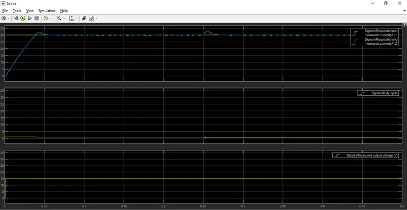
Two Qudrant chopper:
Output:
3. Explain in a brief about operation of BLDC motor.
Answer:
BLDC motor:
A motor converts supplied electrical energy into mechanical energy. Various types of motors are in common use. Among these, brushless DC motors (BLDC) feature high efficiency and excellent controllability, and are widely used in many applications. The BLDC motor has power-saving advantages relative to other motor types.
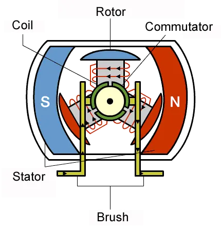
When engineers are faced with the challenge of designing electrical equipment to perform mechanical tasks, they might think about how electrical signals get converted to energy. So actuators and motors are among the devices that convert electrical signals into motion. Motors exchange electrical energy to mechanical energy.
The simplest type of motor is the brushed DC motor. In this type of motor, electrical current is passed through coils that are arranged within a fixed magnetic field. The current generates magnetic fields in the coils; this causes the coil assembly to rotate, as each coil is pushed away from the like pole and pulled toward the unlike pole of the fixed field. To maintain rotation, it is necessary to continually reverse the current—so that coil polarities will continually flip, causing the coils to continue “chasing” the unlike fixed poles. Power to the coils is supplied through fixed conductive brushes that make contact with a rotating commutator; it is the rotation of the commutator that causes the reversal of the current through the coils. The commutator and brushes are the key components distinguishing the brushed DC motor from other motor types
Fixed brushes supply electric energy to the rotating commutator. As the commutator rotates, it continually flips the direction of the current into the coils, reversing the coil polarities so that the coils maintain rightward rotation. The commutator rotates because it is attached to the rotor on which the coils are mounted.
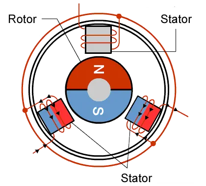
With the brushed motor, rotation is achieved by controlling the magnetic fields generated by the coils on the rotor, while the magnetic field generated by the stationary magnets remains fixed. To change the rotation speed, you change the voltage for the coils. With a BLDC motor, it is the permanent magnet that rotates; rotation is achieved by changing the direction of the magnetic fields generated by the surrounding stationary coils. To control the rotation, you adjust the magnitude and direction of the current into these coils.
- One big advantage is efficiency, as these motors can control continuously at maximum rotational force (torque). Brushed motors, in contrast, reach maximum torque at only certain points in the rotation. For a brushed motor to deliver the same torque as a brushless model, it would need to use larger magnets. This is why even small BLDC motors can deliver considerable power.
- The second big advantage—related to the first—is controllability. BLDC motors can be controlled, using feedback mechanisms, to delivery precisely the desired torque and rotation speed. Precision control in turn reduces energy consumption and heat generation, and—in cases where motors are battery powered—lengthens the battery life.
- The cost of a brushless DC motor is comparatively higher as compared to a brushed DC motor.
- When the Brushless DC motor is operated at low-speed slight vibrations occur during low-speed rotation.
- Brushless DC motor the wiring ad operation of the motor is not that simple due to the involvement of electronic control and its link to all electromagnets.