Project
BAJA ALL TERRAIN VEHICLE ANALYSIS USING SIMULINK:
AIM
To study and analyze the Baja ATV All Terrain Vehicle model using simulink.
OBJECTIVES
* Analyse all components and understand the relation and flow between the blocks
* Understand the different types of ways to model this BAJA ATV
To prepare a technical report on BAJA ATV explaining model properties for the following:
* without using lookup table
* Using lookup table
THEORY:
ATV:
ATV means all-terrain vehicle . It refers to a motorized single seated tri or quadricycle bike and buggy that is designed for off-road ride and activities. An ATV is a small motor vehicle with three or four low-pressure tires designed for use on various types of terrain. ATVs offer excellent off-road capabilities and can carry heavy equipment over long distances and narrow access points.
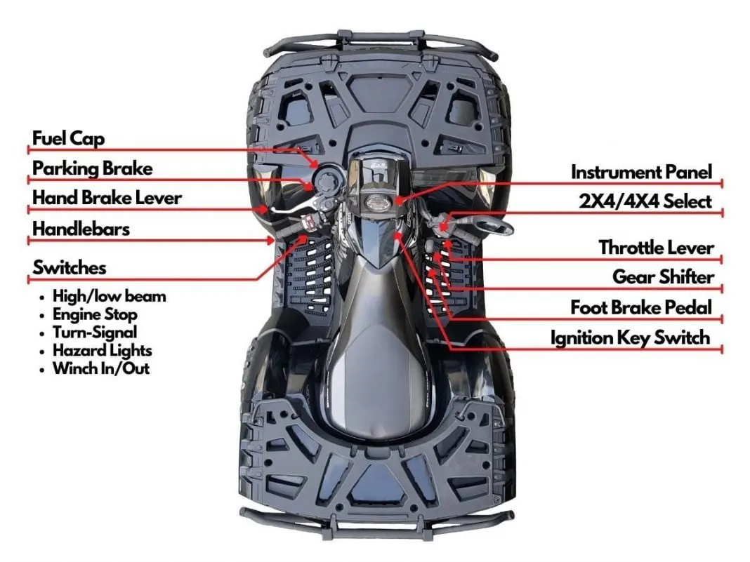
The plots are ,
- Fuel cap
- Parking brake
- Hand Brake Lever
- Handle bars
- Instrumental panel
- 2*4&4*4 select
- Throttle lever
- Gear Shifter
- Foot Brake Pedal
- Ignition Key Switch
-
The main controls on an ATV consist of the handlebars for steering, brake levers for stopping, throttle lever for increasing engine speed and vehicle movement as well as a variety of electrical switches to operate electrical components such as lights, winch, and ignition.
Study:
Part 1 : BAJA ATV MODEL without lookup Table:
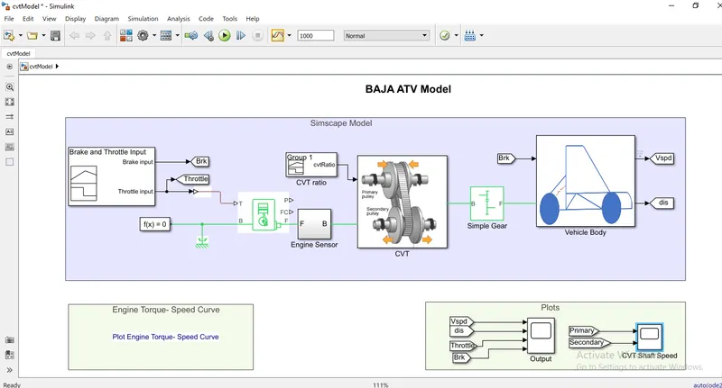
A Simulink model for the BAJA ATV model is shown below
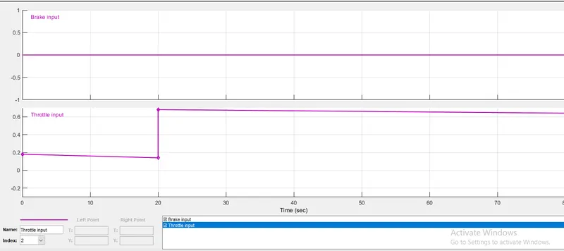
1 Signal Builder Block;
USing the block the brake input signal and the throttle input signal of values 0 and 0.3 respectively proivided to the engine block. Throttle input will control the fuel consumption by the engine such that torque speed input data is provided to the engine . so the required value of torque at a defined speed is produced by the engine with a sufficient amount of fuel consumption
2 Generic Engine ;
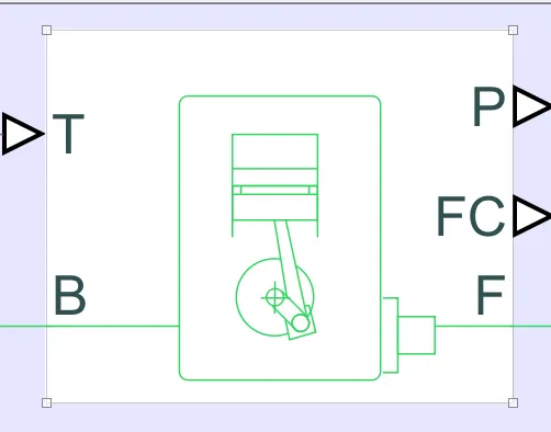
Ports Information:
a, T_port = Engine torque demand as a fraction of maximum possible torque.
b, B_port= Mechanical rotational conserving port associated with the engine block. This is the base port. The engine block is the physical body that contains the piston cylinders.
c, F_port= Mechanical rotational conserving port associated with the engine crankshaft.This is the follower port of the engine.The crankshaft transmits the power generated from the combustion process typically , ypu attach a clutch and transmission at this port.
d, P_port= power produced by the engine , in W
e, FC_port = fuel consumed by the engine , in kg/s
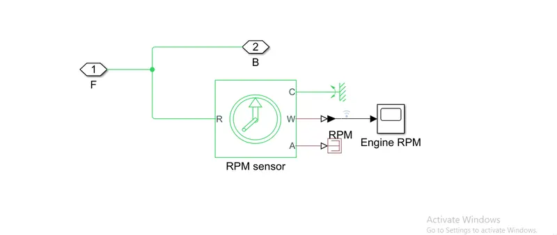
3 , Ideal Rotational Motion Sensor:
The Ideal Rotational Motion Sensor block represents an ideal mechanical rotational motion sensor, that is, a device that converts an across variable measured between two mechanical rotational nodes into a control signal proportional to angular velocity or angle. You can specify the initial angular position (offset) as a block parameter.Connections R and C are mechanical rotational conserving ports and connections W and A are physical signal output ports for velocity and angular displacement,respectively
Simple Gear :
Represents a fixed-ratio gear or gearbox , No intertia or compliance is modeled in this block. You can optionally include gear meshing and viscous bearing losses.
connections B and F are mechanical rotational conserving ports . Specify the relation between base and follower rotation directions with the output shaft rotates parameter.
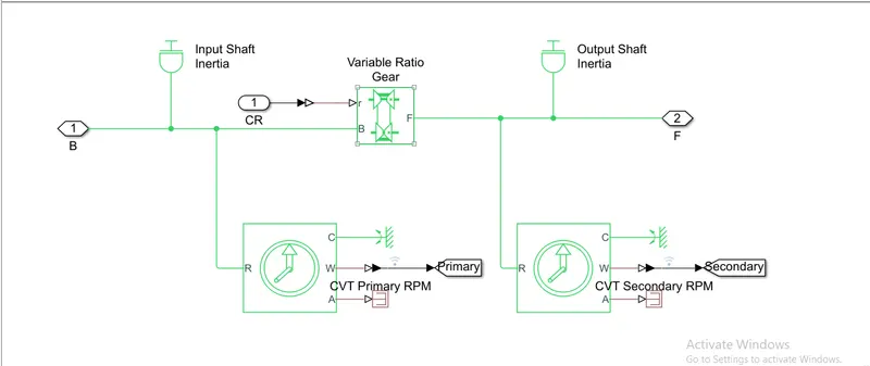
- CVT (continuously variable transmission)
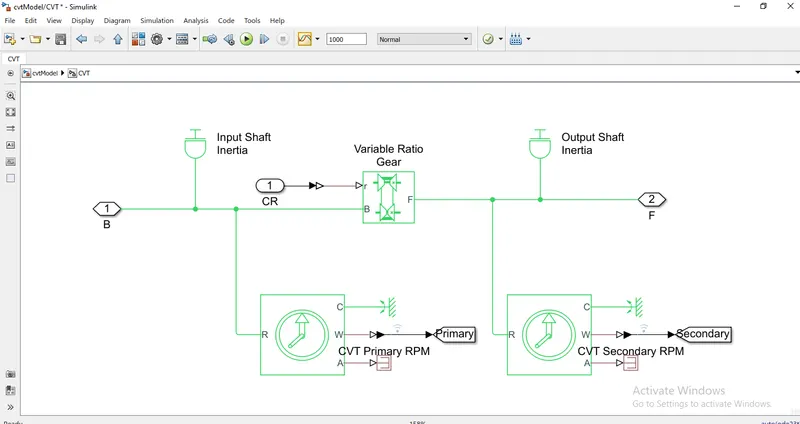
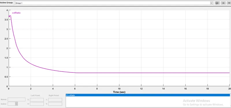
A CVT means continuously variable transmissiion . It is an automatic ,single-speed,and gearless transmission that can shift through an infinite number of gear ratios.This contrasts with other transmissions that provide a limited number of gear ratios in fixed steps. The flexibility of a CVT with suitable control may allow the engine to operate at a constant RRPM while the vehicle moves at varying speeds.
Inertia:
The block represents an ideal mechanical rotational inertia. The block has one mechanical rotational conserving port. The block positive direction is from its port to the reference point. This means that the inertia torque is positive if the inertia is accelerated in a positive direction .
Variable Ratio Transmission :
Represents a variable ratio gearbox such as implemented by mechanical belt CVT.electric or hydraulic transmissions. The physical signal input are defines the ratio of input to output angular shaft velocities .
Connections B and F are mechanical rotational conserving ports . specify the relation between base and follwer rotation directions with the output shaft rotates parameter.
CVT RATIO:
Engine Sensor:
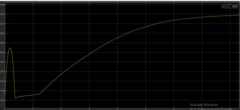
Engine RPM:
Vehicle body;
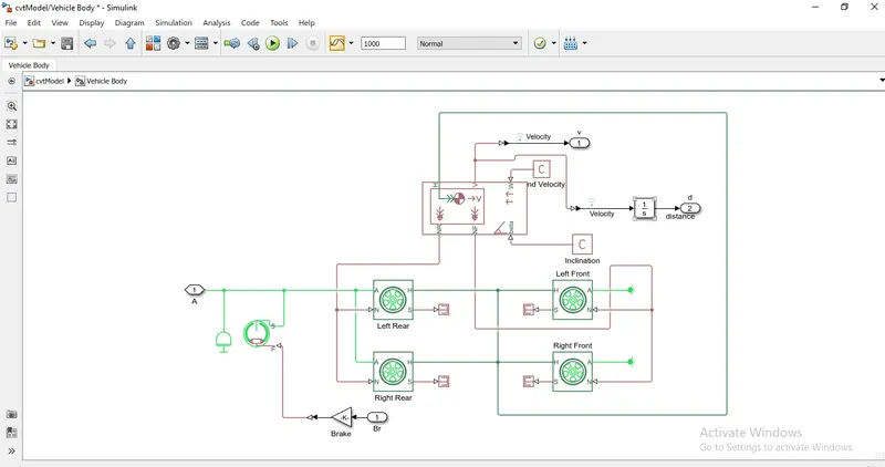
* Inertia - The block represents an ideal mechanical rotational inertia.
* Double Shoe Brake - Represents a brake arranged as two pivoted rigid shoes symmetrically installed inside and operated by one actutor.
* Gain- Element-wise gain (y=k*u) or matrix gain
* Tyre - Represents the longitudinal behavior of a highway tire characterized by the tire magic formula
* PS terminator - Use this block to terminate physical signal outputs
* PS Constant- This block creates a physical signal constant
* PS-Simulink convertor - Converts the input physical signal to a simulink output signal.
* Integrator - The Integrator block outputs the value of the integral of its input signal with respect to the time
* Scope - Display signals generated during simulation
RESULT
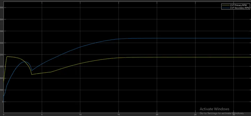
Primary and Secondary Shaft Speed;
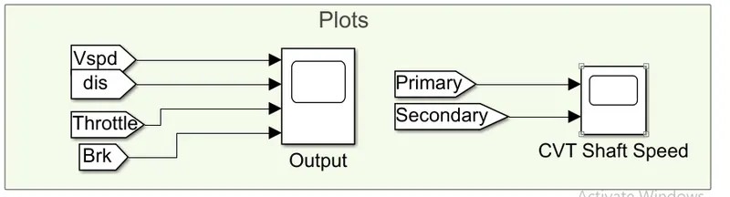
1) Simulation run time is 200 sec,
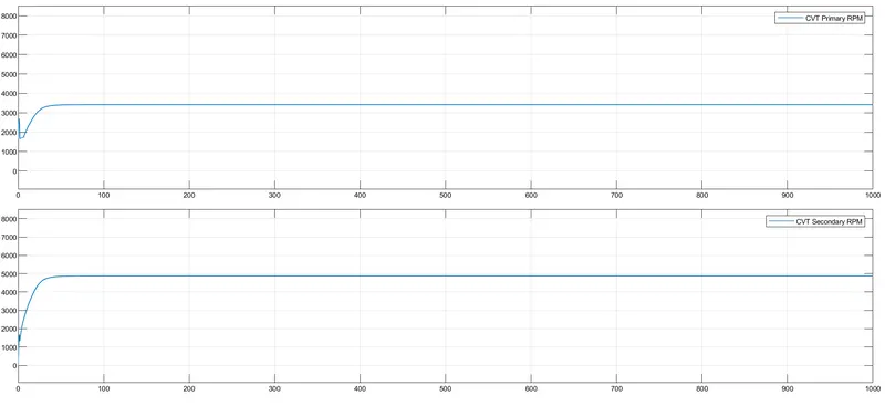
- Initial velocity/rpm of engine is defined as the 1750rpm , then as the throttle vlaue is constant input the rpm of engine changes accordingly
- And since the throttle value is constant through the complete simulation after a certain duration engine rpm becomes constant.
- As the primary shaft is connected to the engine it looks similar to the engine rpm but due to the inertia and other factors the primary shaft rpm will not be the same as the engine rpm and it will have some losses
- Hence primary shaft will not be the same as the engine but will have similar rpm with considering some losses.
- And according to the CVT ratio the secondary shaft speed is achieved .
OUTPUT:
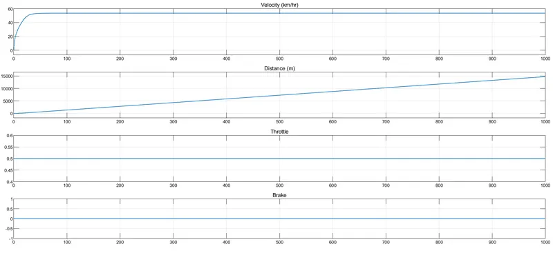
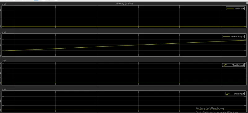
- We can verify that the throttle value and brake value are constant during the complete simulation.
- Initially , the velocity of the vehicle is increased rapidly and then after a certian point when the engine reaches its constant rpm, the velocity of the vehicle becomes constant
- As we know integration of the velocity gives us the distance travel by vehicle.
- Hence during the initial simulation time , the distance traveled looks like a parabolic curve , and then as velocity becomes constant the distance traveled becomes a straight line.
- Part 2: Baja atv model
2, Using lookup table:
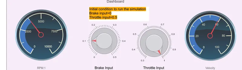
A simulink model for the BAJA ATV model including the dashboard and the lookup table is shown below
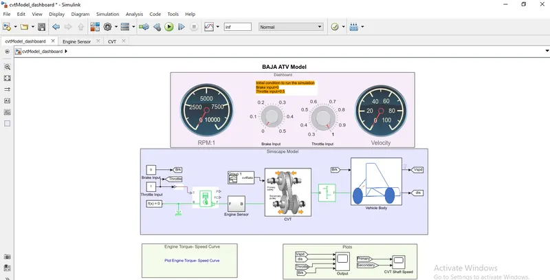
Explanation of the model:
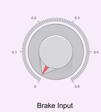
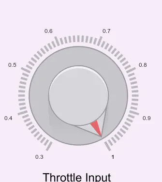
- In the model we can change the input values of throttle and brake with the help of knobs
- In this model the simulation runtime is kept at infinity so that we can change the values of the throtlte and brake during the simulation run to get the real time effect of the input parameters
- We also have two circular gauges which are connected to measure the rpm of the engine and velocity of the vehicle
Input;
It comprises a throttle and brake input through a knob which can be unlike the signal builder in the previous model without dashboard . The engine RPM gauge and velocity gauge displays the changes done by the respective knobs.
CVT:
Input value:
Output:
Conclusion:
All the model results are reported and observations are described which explains how a CVT model behaves when different ways of inputs were given and shown different simscape model ways.