Project-1: Powertrain for aircraft in runways
Part A:
1. Search and list out the total weight of various types of aircrafts.
2. Is there any difference between ground speed and air speed?
3. Why is it not recommended to use aircraft engine power to move it on the ground at Airport?
4. How an aircraft is pushed to runway when its ready to take off?
5. Learn about take off power, tyre design, rolling resistance, tyre pressure, brake forces when landing.
Part B:
6. A. With necessary assumptions, calculate the force and power required to push / pull an aircraft by a towing vehicle.
B. Develop the model for the calculated force and power using Simulink.
7. A. Design an electric powertrain with type of motor, it’s power rating, and energy requirement to fulfill aircraft towing application in Simulink. Estimate the duty cycle range to control the aircraft speed from zero to highest. Make all required assumptions. Prepare a table of assumed parameters. Draw a block diagram of powertrain.
(Hint :DC7 Block)
B. Also, Design the parameters in excel sheet.
Solution:
1. Search and list out the total weight of various types of aircrafts.
Types of Aircraft:
Aircraft gross weight
The aircraft gross weight (also known as the all-up weight and abbreviated AUW) is the total aircraft weight at any moment during the flight or ground operation.
An aircraft's gross weight will decrease during a flight due to fuel and oil consumption. An aircraft's gross weight may also vary during a flight due to payload dropping .
At the moment of releasing its brakes, the gross weight of an aircraft is equal to its takeoff weight. During flight, an aircraft's gross weight is referred to as the en-route weight or in-flight weight.
1, Gliders:
- Hang gliders are aircraft of various configurations in which the pilot is suspended beneath the (usually fabric) wing to provide stability and control.
- They are normally launched from a high point. In the hands of an experienced pilot, hang gliders are capable of (using soaring rising air columns to obtain upward gliding movement).
- Gliders are usually used for flight training and have the capability to fly reasonable distances when they are catapulted or towed into the air, but they lack the dynamic sophistication of Sailplanes. These sophisticated unpowered craft have wings of unusually high aspect ratio (that is, a long wing span in proportion to wing width).
- Most sailplanes are towed to launch altitude, although some employ small, retractable auxillary engines. They are able to use thermals (currents more buoyant than the surrounding air, usually caused by higher temperature) and orographic lift to climb to higher altitude and to glide for great distances.
- Orographic lift results from the mechanical effect of wind blowing against a terrain feature such as a cliff. The force of the wind is deflected upward by the face of the terrain, resulting in a rising current of air.
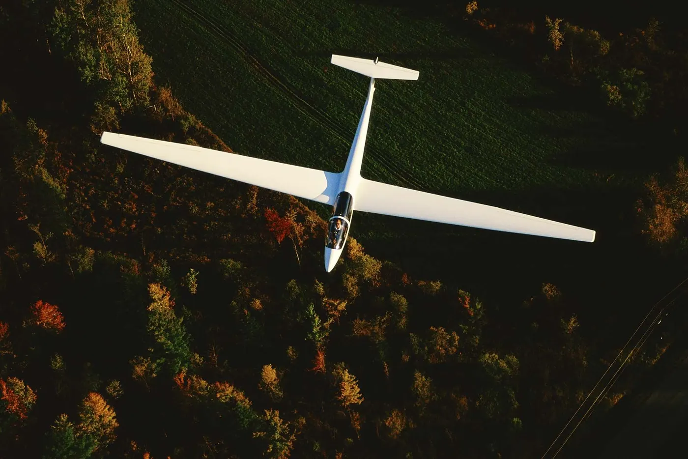
Weight of Glider planes : 110 kg - 200 kg
2, Maximum takeoff weight (MTOW)
The maximum takeoff weight (MTOW) or maximum gross takeoff weight (MGTOW) or maximum takeoff mass (MTOM) of an aircraft is the maximum weight at which the pilot is allowed to attempt to takeoff, due to structural or other limits. The analogous term for rockets is gross lift-off mass, or GLOW. MTOW is usually specified in units of kilograms or pounds.
MTOW is the heaviest weight at which the aircraft has been shown to meet all the airworthiness requirements applicable to it. MTOW of an aircraft is fixed and does not vary with altitude, air temperature, or the length of the runway to be used for takeoff or landing.
Maximum permissible takeoff weight or "regulated takeoff weight", varies according to flap setting, altitude, air temperature, length of runway and other factors. It is different from one takeoff to the next, but can never be higher than the MTOW.
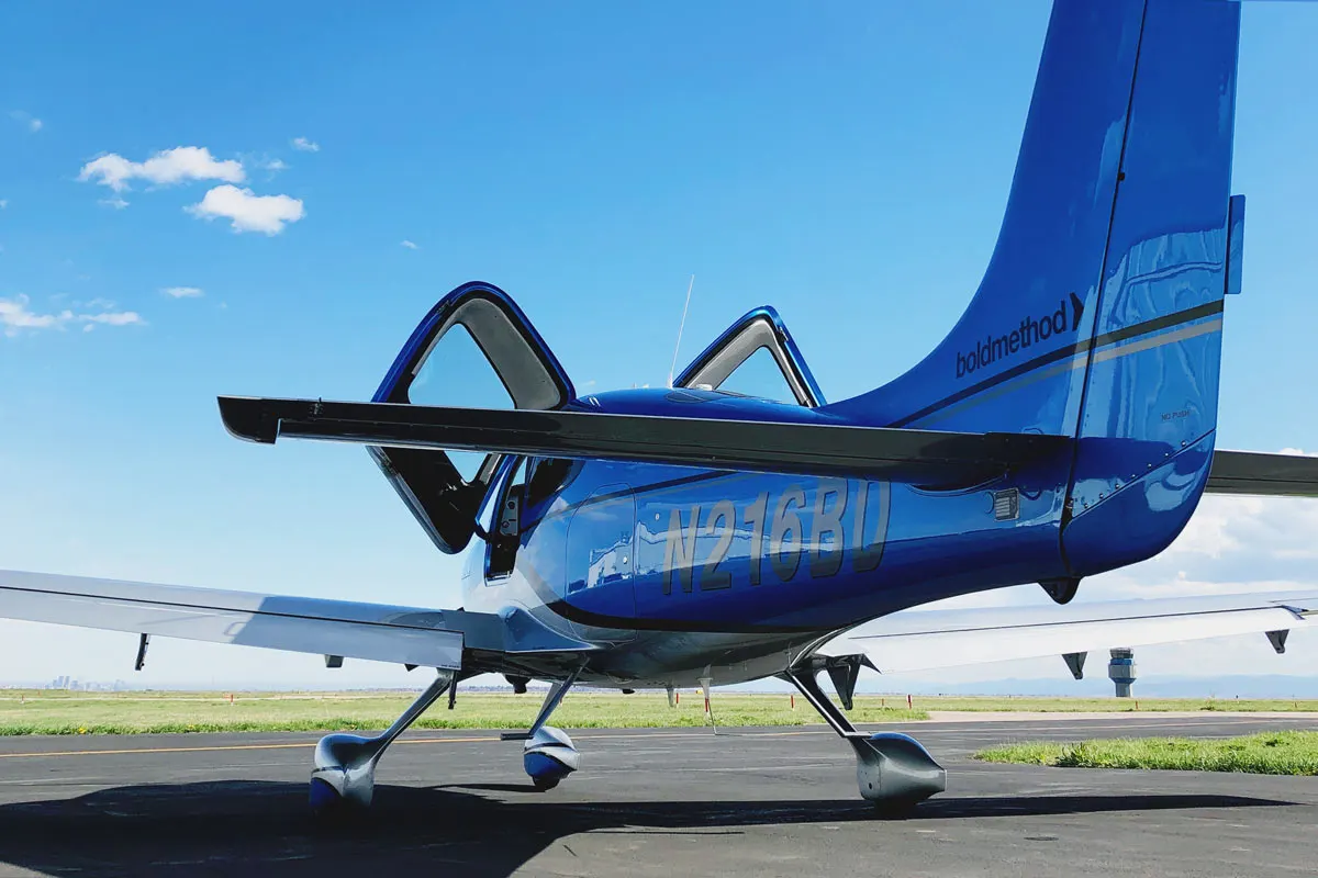
3, Minimum flight weight (MFW).
It's MTOW is around 75,000 lbs, allowing for around 33,000 lb combinations of passengers, cargo, and fuel. The 42,000 lb "minimum weight" (also listed as 44,000 lbs) would be a useful tool to determine safe loading of the aircraft. But one other criteria for loading is Center of Gravity.
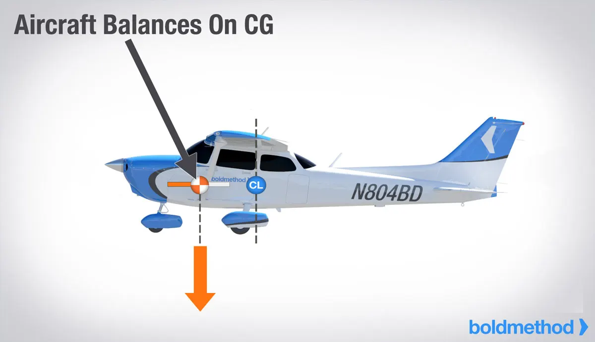
4, Maximum ramp weight:
The maximum ramp weight (MRW) (also known as the maximum taxi weight (MTW)) is the maximum weight authorised for manoeuvring (taxiing or towing) an aircraft on the ground as limited by aircraft strength and airworthiness requirements. It includes the weight of taxi and run-up fuel for the engines and the auxiliary power unit (APU).
It is greater than the maximum takeoff weight due to the fuel that will be burned during the taxi and run-up operations.
The difference between the maximum taxi/ramp weight and the maximum take-off weight (maximum taxi fuel allowance) depends on the size of the aircraft, the number of engines, APU operation, and engines/APU fuel consumption, and is typically assumed for 10 to 15 minutes allowance of taxi and run-up operations.
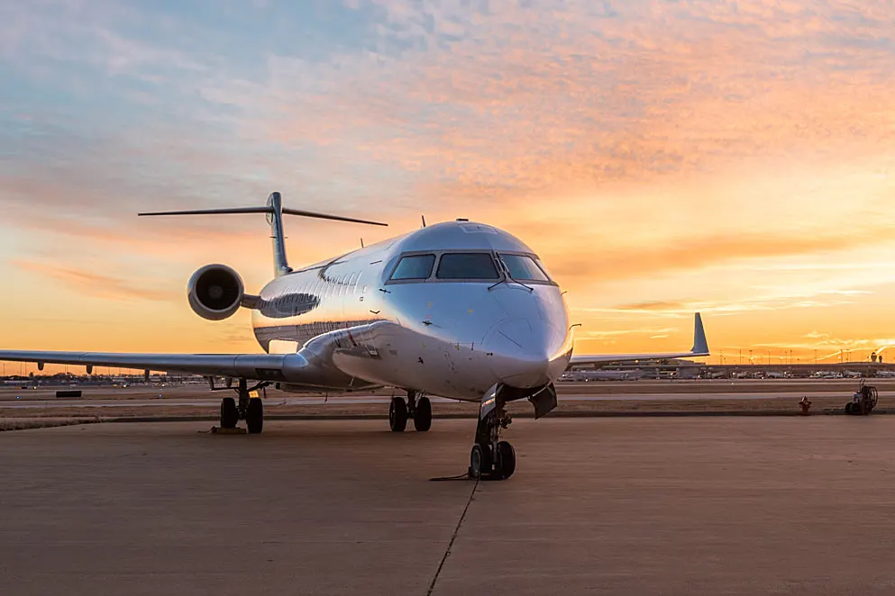
MTOW = Maximum take-off weight, MLW = Maximum landing weight, TOR = Take-off run (SL, ISA+15°, MTOW), LR = Landing run (SL, ISA+15°, MLW)
| Type | MTOW [kg] | MLW [tonnes] | TOR [m] | LR [m] | ICAO category | FAA category |
|---|---|---|---|---|---|---|
| Antonov An-225 | 640,000 | 591.7 | 3,500 | Heavy | Super | |
| Scaled Composites Model 351 Stratolaunch | 589,670 | 3,660 | Heavy | Super | ||
| Airbus A380-800[1][2][3] | 575,000 | 394 | 3,100 | 1,930 | Heavy | Super |
| Boeing 747-8F | 447,700 | 346.091 | 3,100 | 1,800 | Heavy | Heavy |
| Boeing 747-8 | 443,613 | 306.175 | 3,100 | Heavy | Heavy | |
| Boeing 747-400ER | 412,770 | 295.742 | 3,090 | Heavy | Heavy | |
| Antonov An-124-100M | 405,060 | 330 | 2,520 | 900 | Heavy | Heavy |
| Boeing 747-400 | 396,900 | 295.742 | 3,018 | 2,179 | Heavy | Heavy |
| Lockheed C-5 Galaxy[4][5][6] | 381,000 | 288.417 | 2,530 | 1,494 | Heavy | Heavy |
| Boeing 747-200[7] | 377,840 | 285.7 | 3,338 | 2,109 | Heavy | Heavy |
| Boeing 747-300[7] | 377,840 | 260.32 | 3,222 | 1,905 | Heavy | Heavy |
| Airbus A340-500[8] | 371,950 | 240 | 3,050 | 2,010 | Heavy | Heavy |
| Airbus A340-600[8] | 367,400 | 256 | 3,100 | 2,100 | Heavy | Heavy |
| Boeing 777F | 347,800 | 260.816 | 2,830 | Heavy | Heavy | |
| Boeing 777-300ER | 351,800 | 251.29 | 3,100 | Heavy | Heavy | |
| Boeing 777-200LR | 347,450 | 223.168 | 3,000 | Heavy | Heavy | |
| Boeing 747-100[7] | 340,200 | 265.3 | Heavy | Heavy | ||
| Airbus A350-1000 | 308,000 | 233.5 | Heavy | Heavy | ||
| Boeing 777-300 | 299,370 | 237.683 | 3,380 | Heavy | Heavy | |
| Boeing 777-200ER | 297,550 | 213 | 3,380 | 1,550 | Heavy | Heavy |
| Airbus A340-300[8][9] | 276,700 | 190 | 3000 | 1926 | Heavy | Heavy |
| McDonnell Douglas MD-11 | 273,300 | 185 | 2,990 | 1,890 | Heavy | Heavy |
| Airbus A350-900 | 270,000 | 175 | 2,670 | 1,860 | Heavy | Heavy |
| Ilyushin Il-96M | 270,000 | 195.04 | 3,115 | 2,118 | Heavy | Heavy |
| McDonnell Douglas DC-10 | 256,280 | 183 | 2,990 | 1,890 | Heavy | Heavy |
| Boeing 787-9[10] | 254,000 | 192.777 | 2,900 | Heavy | Heavy | |
| Boeing 787-10[10] | 254,000 | 201.849 | Heavy | Heavy | ||
| Airbus A340-200[8][11] | 253,500 | 181 | 2990 | Heavy | Heavy | |
| Airbus A330-900 | 251,000 | 191 | 3,100 | Heavy | Heavy | |
| Ilyushin IL-96-300 | 250,000 | 175 | 2,600 | 1,980 | Heavy | Heavy |
| Airbus A330-300[12][13] | 242,000 | 185 | 2500 | 1750 | Heavy | Heavy |
| Airbus A330-200[12][13] | 242,000 | 180 | 2,220 | 1,750 | Heavy | Heavy |
| Lockheed L-1011-500 | 231,300 | 166.92 | 2,636 | Heavy | Heavy | |
| Boeing 787-8[10] | 228,000 | 172.365 | 3,300 | 1,695 | Heavy | Heavy |
| Lockheed L-1011-200 | 211,400 | Heavy | Heavy | |||
| Ilyushin IL-86 | 208,000 | 175 | Heavy | Heavy | ||
| Boeing 767-400ER | 204,000 | 158.758 | 3,414 | Heavy | Heavy | |
| Airbus A300-600R[14] | 192,000 | 140 | 2,385 | 1,555 | Heavy | Heavy |
| Boeing 767-300ER | 187,000 | 136.08 | 2,713 | 1,676 | Heavy | Heavy |
| Concorde | 185,000 | 111.1 | 3,440 | 2,220 | Heavy | Heavy |
| Airbus A300-600[14] | 163,000 | 138 | 2,324 | 1,536 | Heavy | Heavy |
| Boeing 767-300 | 159,000 | 136.078 | 2,713 | 1,676 | Heavy | Heavy |
| Airbus A310-300[14] | 157,000 | 124 | 2,290 | 1,490 | Heavy | Heavy |
| Vickers VC10 | 152,000 | 151.9 | Heavy | Heavy | ||
| Boeing 707-320B[15] | 151,000 | 97.5 | Heavy | Heavy | ||
| Boeing 707-320C[15] | 151,000 | 112.1 | Heavy | Heavy | ||
| Douglas DC-8-61 | 147,000 | Heavy | Heavy | |||
| Airbus A310-200[14] | 142,000 | 123 | 1,860 | 1,480 | Heavy | Heavy |
2. Is there any difference between ground speed and air speed?
Generally speaking, there are two different types of speed when talking about airplanes: ground speed and airspeed.
Ground speed is the airplane’s speed relative to the surface of the Earth, airspeed – at least true airspeed – is its speed relative to the air it is flying in.
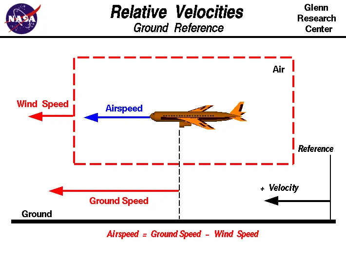
The relationship between airspeed and ground speed is fairly simple. Ground speed is simply the sum of airspeed and wind speed.
If the aircraft is flying in the same direction as the wind is blowing, the aircraft experiences tailwind, and its ground speed is higher than its airspeed. On the other hand, if the wind is blowing against the direction the aircraft is traveling in, the aircraft experiences headwind, and its ground speed is lower than its airspeed.
Ground Speed
For a reference point picked on the ground, the aircraft moves relative to the reference point at the ground speed. Ground speed is also a vector quantity so a comparison of the ground speed to the wind speed must be done according to rules for vector comparisons
Airspeed
The important quantity in the generation of lift is the relative velocity between the object and the air, which is called the airspeed. Airspeed cannot be directly measured from a ground position, but must be computed from the ground speed and the wind speed. Airspeed is the vector difference between the ground speed and the wind speed.
Airspeed = Ground Speed - Wind Speed
On a perfectly still day, the airspeed is equal to the ground speed. But if the wind is blowing in the same direction that the aircraft is moving, the airspeed will be less than the ground speed.
3. Why is it not recommended to use aircraft engine power to move it on the ground at Airport?
Although many aircrafts are capable of moving in backward using reverse thrust, as result the jet blast or prop wash might cause damage to the terminal building or equipment. Engine close to ground may also blow sand and debris forward and then suck them into the engine, causing damage to the engine
Towing is coupling two or more objects together so that they may be pulled by a designated power source or sources. The towing source may be a motorized land vehicle, vessel, animal, or human, and the load being anything that can be pulled
Although many aircraft are capable of moving themselves backwards on the ground using reverse thrust (a procedure referred to as a powerback), the resulting jet prop might cause damage to the terminal building or equipment. Engines close to the ground may also blow sand and debris forward and then suck them into the engine, causing damage to the engine. A pushback is therefore the preferred method to move the aircraft away from the gate.
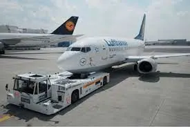
Although most aircraft are capable of moving themselves backwards on the ground using reverse thrust, a procedure called as a powerback, it is not typically done due to the following reasons:
- The jet blast from the engines can damage the terminal building and nearby equipment. It can even throw away people standing nearby.
- Engines can blow sand and debris.
- Engines can suck in sand and debris which can cause serious damage to the engine.
- It is easier for the truck driver to see the surroundings better than the pilot sitting in the cockpit with limited windows.
- The pushback truck driver knows the airport better than the pilot.
- The plane engines are very loud. This noise can add up substantially when multiple planes are moving around the airport. It won't be a pleasant experience for people sitting inside the terminal, as most people don't even like the sound of powerful motor-bikes.
- It saves fuel. Virgin Atlantic had proposed a new system in which the pushback trucks will push the plane all the way to the runway to save fuel and reduce impact on nearby environment.
4. How an aircraft is pushed to runway when its ready to take off?
Pushback is when an aircraft is pushed backwards away from the airport gate by vehicles called tugs or tractors. Closer to departure, an aircraft tug will park right in front of the nose wheel. The tug might be directly attached to the plane's nose gear with a tow bar, or could be a "wheel-lift" tug.
- The pilot parks the aircraft in exactly the right place. Usually with the help of an automatic system, but occasionally guided by a marshaller waving two paddles or wands. Dozens of handling personnel are already standing by to perform a whole range of tasks simultaneously.
- As soon as the aircraft is stationary and the engines are switched off, the first priority is to disembark the passengers as quickly as possible. The apron handler places chocks in front of the wheels and connects the ground power. Meanwhile, the passenger bridge manoeuvres up to the door and a belt loader rolls up to the cargo hold. Luggage is unloaded and transferred to the terminal on baggage carts.
- Refuelling begins, usually from a hydrant at the stand. A hose is attached to this from a special vehicle called a dispenser, with the other side connected to the fuel tank in the wing. Read more about refuelling .
- Now it is time to service the aircraft. The caterer loads new meals and takes away the food waste and used cutlery and crockery. Other activities include draining the lavatories, replacing the headrest covers, removing rubbish and distributing fresh blankets and in-flight magazine.
- A specialist team – or sometimes the crew themselves – cleans the cabin so that the new passengers board a pristine aircraft.
- Meanwhile, specialists from the airline conduct a technical check to make sure that the engines, wings, control surfaces, landing gear, instruments, doors and other equipment are in full working order.
- The aircraft is now ready for baggage to be loaded for the next flight. This is a quick process, on average taking only 10-15 minutes. A little later the passengers start boarding. As soon as they are all in their seats, the door is closed and the pilot informs air-traffic control that the flight is ready for departure.
- The apron handler removes the chocks. A so-called pushback truck reverses the aircraft into taxiing position, pushing it with a towbar attached to the nose-wheel strut. Or, in the most modern versions, by actually lifting the wheel. That speeds up coupling and decoupling.
- The aircraft taxis to the runway to depart at the agreed time.
- The pilot waits for permission to take off from air-traffic control. This is possible once the departure route is clear. As soon as the go-ahead is received, the plane takes to the air at full power.
5. Learn about take off power, tyre design, rolling resistance, tyre pressure, brake forces when landing.
Take off power:
Take off performance can be predicted using a simple measure of the acceleration of the aircraft along the runway based on force equilibrium.
The forces involved will be,
T – Thrust of propulsion system pushing aircraft along runway.
D – Aerodynamic Drag of vehicle resisting the aircraft motion.
F – Rolling resistance friction due to the contact of wheels or skids on the ground.
During take-off run the imbalance in these forces will produce an acceleration along the runway.
dv/dt = T - D - F/m
where dV/dt is the acceleration along the runway and m is the mass of the vehicle.
Rotation velocity,
The procedure for take-off will be that the vehicle will accelerate until it reaches a safe initial flying speed. The pilot can then rotate the vehicle to an attitude to produce climb lift and it will ascend from the ground. The determination of this safe flying speed or rotation speed, VR, is a critical factor in determining take-off performance.
Take-off rules vary slightly depending on the aircraft category. Small commuter aircraft should be considered as meeting FAR 23 rules, transport category aircraft should comply with FAR 25 rules.
V1- Abort decision speed. Below this speed the take-off can be safely aborted. After this there will not be sufficient runway length to allow the aircraft to decelerate to a stop.
V2 – Safe climb speed. V2 must be no less than 1.2 * Vstall. Below this speed aircraft cannot attain sufficient climb rate.
Transport Aircraft :
VR must not be less than V1
VR must be greater than 1.05 * VMC
VR must be set so that aircraft achieves V2 before reaching a height of 35ft above the runway surface.
Aircraft must climb at a minimum gradient to avoid obstacles at the end of the runway. With engine failure on multi-engined aircraft, this speed should still be achievable.
Tyre Design:
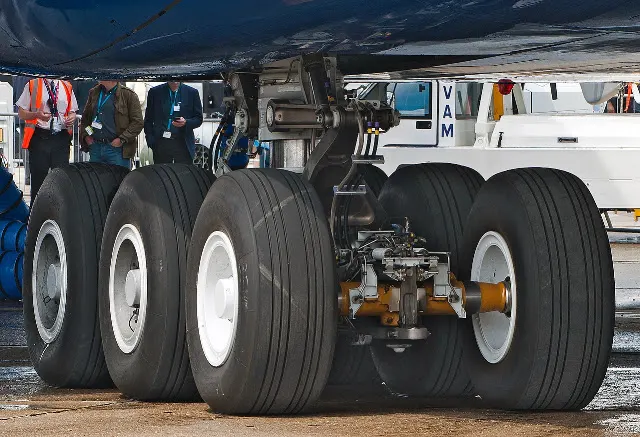
The aircraft tire is a combined structure of these basic materials:
- Rubber
- Nylon
- Cord
- Steel
These tires are combined together by a vulcanization process. Vulcanization process is a chemical process for converting polymers into more durable materials by introducing crosslinks. This process of treating crude or synthetic rubber or similar plastic material chemically to give it useful properties (such as elasticity, strength, and stability). There are mainly two types of tires:- Radial and Bias, each type has unique components reflecting different technologies applied to design, compounds and materials. To understand the difference between these two different types of tires, you have to first understand the meaning of ply rating. Ply rating is a rating of how many layers of rubber is on a tire. The number of layers of rubber and the angles at which they are laid dictate the strength and load capacity of the tire.
Bias-Ply Tire
The bias ply tire consists of layers of rubber running diagonally at approximately right angles to one another The bias tire are currently in maximum because of their strength. ITF (Inter Tread Reinforcing Fabric) is used in a bias tire. It provides additional high-speed stability, reduces tread distortion under load, protects the casing plies from damage and can act as wear indicators on re-manufactured tires.
Radial Ply Tire
In aircraft with radial ply tires, tires have layers of the tire running radially at an approximate perpendicular to the center line of the tire. Radial ply tires are low in weight as compared to the bias ply tire but have less strength.
Different Components Of Tire
Tread
It is a special composite rubber formulated to resist wear and tear, cutting, chunking, and heat build-up. Circumferential grooves are molded into the tread to disperse water from beneath the tread in wet runway conditions. The tread also helps to reduce the risk of aqua planning and improves traction and grip between the tread and runway surface.
Shoulder
Tire shoulder is the portion of the tread between the tread center and the tire sidewall. The tire shoulder offers support and protection to both the sidewall and the tread. The shoulder is a thick part of the tire, enabling the tire to more easily hold its form during cornering maneuvers.
Casing
The foundation strength of the tire is provided by the casing plies. Casing plies are layers of fabric coated with the high modulus of elasticity rubber on both sides to improve its elastic strength. Casing plies are wrapped around the beads (Bead is a wire used for attaching two things very strongly) for proper fitting.
Beads
The bead wire attaches the tire to the rim and ensures an airtight seal. Bead consist of bundles of high-tensile steel wires, each strand of which is coated in rubber compound and wound into coils of the correct diameter for given tire size.
Chafers
Chafers are made of tough nylon material and are fitted around the bead clinch area to resist chafing damage (It is damage caused to the skin of tire due to repetitive rubbing) to both tire and rim flange.
Sidewall
The sidewall is the area of the tire between the shoulder and the bead. The sidewalls of the tire are covered with a layer of specially formulated rubber treated with anti-oxidants. The sidewall of the tire protects the casing from the effects of weathering and offers resistance to cuts and flexing.
Inner tread
Tubeless tires have a layer of rubber bonded to the inside of the first casing ply from bead to bead to resist the permeation of nitrogen and moisture into the casing.
Under tread
The under tread is a layer of rubber that is designed to improve the adhesion between the tread and the casing plies.
Rolling resistance:
The friction between aircraft and runway will be proportional to the normal force exerted by the aircraft on the runway.
The normal force will be the difference between Weight of aircraft and Lift, the friction coefficient will be typically of a magnitude of 0.02 for a standard tarmac runway.
The rate of change of velocity can be predicted at any point on the take-off roll by substituting results for T, D and F into the initial equation for dV/dt. The subsequent velocity at any point can be found by integrating this resulting equation and the distance traveled found by then integrating the velocity.
Typically acceleration will be dominated by the drag component as thrust, weight and friction are relatively constant during this period. This leads to the result shown where acceleration is inversely proportional to velocity squared.
The rolling resistance can be expressed as
Fr = c W (1)
where
Fr = rolling resistance or rolling friction (N, lbf)
c = rolling resistance coefficient - dimensionless (coefficient of rolling friction - CRF)
W = m ag
= normal force - or weight - of the body (N, lbf)
m = mass of body (kg, lb)
ag = acceleration of gravity (9.81 m/s2, 32.174 ft/s2)
| Rolling Resistance Coefficient | ||
|---|---|---|
| c | cl (mm) | |
| 0.001 - 0.002 | 0.5 | railroad steel wheels on steel rails |
| 0.001 | bicycle tire on wooden track | |
| 0.002 - 0.005 | low resistance tubeless tires | |
| 0.002 | bicycle tire on concrete | |
| 0.004 | bicycle tire on asphalt road | |
| 0.005 | dirty tram rails | |
| 0.006 - 0.01 | truck tire on asphalt | |
| 0.008 | bicycle tire on rough paved road | |
| 0.01 - 0.015 | ordinary car tires on concrete, new asphalt, cobbles small new | |
| 0.02 | car tires on tar or asphalt | |
| 0.02 | car tires on gravel - rolled new | |
| 0.03 | car tires on cobbles - large worn | |
| 0.04 - 0.08 | car tire on solid sand, gravel loose worn, soil medium hard | |
| 0.2 - 0.4 | car tire on loose sand | |
Tyre pressure:
The high-flying rubber is typically inflated to 200 psi, roughly six times what you put in an automobile tire, and the tires on an F-16 fighter are pumped to 320 psi.
| Size | Ply Rating | Max. Load (per tire) | Unloaded Inflation (psi) |
| 10/350-4 | 4 | 460 | 60 |
| 12.5-4.5 | 10 | 1800 | 75 |
| 18-5.5 | 8 | 3050 | 105 |
| 22/800-8 | 6 | 2500 | 40 |
| 27" SC | 10 | 5500 | 50 |
| 29/1100-10 | 10 | 7070 | 60 |
| 280/250-4 | 4 | 395 | 60 |
| 5.00-4, 500x4, 5.00x4 | 6 | 1200 | 55 |
| 5.00-4, 500x4, 5.00x4 | 14 | 2550 | 115 |
| 5.00-5, 500x5, 5.00x5 | 4 | 800 | 31 |
| 5.00-5, 500x5, 5.00x5 | 6 | 1285 | 50 |
| 5.00-5, 500x5, 5.00x5 | 10 | 2150 | 88 |
| 6.00-6, 600x6, 6.00x6 | 4 | 1150 | 29 |
| 6.00-6, 600x6, 6.00x6 | 6 | 1750 | 42 |
| 6.00-6, 600x6, 6.00x6 | 8 | 2350 | 55 |
| 7.00-6, 700x6, 7.00x6 | 6 | 1900 | 38 |
| 7.00-6, 700x6, 7.00x6 | 8 | 2550 | 54 |
| 8.00-4, 800x4, 8.00x4 | 4 | 1100 | 24 |
| 8.00-6, 800x6, 8.00x6 | 4 | 1350 | 23 |
| 8.00-6, 800x6, 8.00x6 | 6 | 2050 | 35 |
| 8.00-6, 800x6, 8.00x6 | 8 | 2800 | 48 |
| 8.50-6, 850x6, 8.50x6 | 6 | 2275 | 30 |
| 9.00-6, 900x6, 9.00x6 | 10 | 4500 | 58 |
| 6.50-8, 650x8, 6.50x8 | 6 | 2300 | 51 |
| 6.50-8, 650x8, 6.50x8 | 8 | 3150 | 75 |
| 7.00-8, 700x8, 7.00x8 | 6 | 2400 | 46 |
| 6.50-10, 650x10, 6.50x10 | 6 | 2770 | 60 |
| 6.50-10, 650x10, 6.50x10 | 8 | 3750 | 80 |
| 6.50-10, 650x10, 6.50x10 | 10 | 4750 | 100 |
| 6.50-10, 650x10, 6.50x10 | 12 | 5750 | 120 |
| 8.50-10, 850x10, 8.50x10 | 6 | 3250 | 41 |
| 8.50-10, 850x10, 8.50x10 | 8 | 4400 | 55 |
| 8.50-10, 850x10, 8.50x10 | 10 | 5500 | 70 |
| 11.00-12, 1100x12, 11.00x12 | 8 | 6300 | 45 |
| 11.00-12, 1100x12, 11.00x12 | 10 | 8200 | 60 |
| 750-10 | 6 | 3000 | 46 |
| 890-12.50 | 6 | 4300 | 50 |
6. A. With necessary assumptions, calculate the force and power required to push / pull an aircraft by a towing vehicle.
The force to move an airplane on an absolute flat runway with no wind at constant low speed is equal to the rolling resistance between the plane and the tarmac.
The rolling resistance for the air plane can be calculated as
Fr = c mr ag (1)
where
Fr = rolling resistance (N, lbf)
c = rolling resistance coefficient
mr = rolling mass (kg, lbm)
ag = acceleration of gravity (9.81 m/s2)
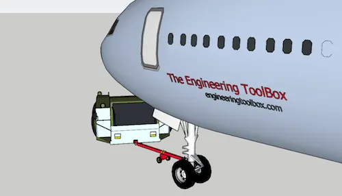
If the mass of a plane is 40000 kg rolling coefficient and the between the aircraft wheel and the tarmac is 0.02 - the force required to overcome the rolling resistance can be calculated as
Fr = 0.02 (40000 kg) (9.81 m/s2)
= 7848 N
This force can be delivered by a pulling truck or - as occasionally seen - by a number of pulling people. Enough weight for the pullers are required to create friction forces against the tarmac that equals the plane rolling resistance.
The friction force for the puller can be calculated to
Ff = μ W
= μ mf ag (2)
where
Ff = frictional force (N, lb)
μ = friction coefficient
W = weight (N, lbf)
mf = friction mass (kg)
The friction coefficient between a pulling truck rubber wheels and dry tarmac is 0.9. Since pulling trucks are connected to air crafts nose wheels close to tarmac we simplify the calculation of required truck mass to
mf = (7848 N) / (0.9 (9.81 m/s2))
= 889 kg
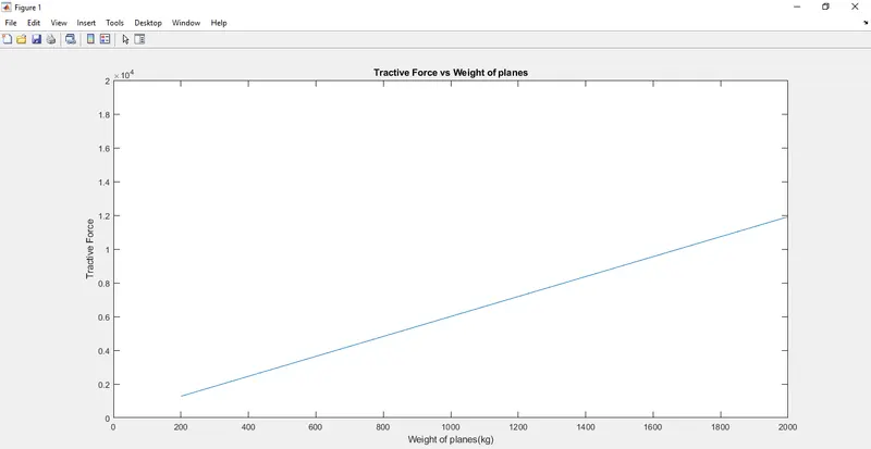
Now we use a script from matlab which will help us calculate the pulling force required :
clc
clear all

%Inputs
c=0.002%Rolling resistance coefficient
m=linspace(200,25000,2000) % Weight
g=9.81 %acceleration of gravity
u=0.6%friction coefficient
A=linspace(50,100,2000)%area of planes
v=2 % velocity
Cd=0.8 %Drag Coefficient
%Calculations

F1=c*m*g %Rolling resistance force
F2=u*g*m%Friction force
F3=0.5*A*1.2*Cd*(v)^2
Ft=F1+F2+F3

plot(m,Ft)
title('Tractive Force vs Weight of planes')
xlabel('Weight of planes(kg)')
ylabel('Tractive Force')
axis([0 2000 0 20000])
Result:
B. Develop the model for the calculated force and power using Simulink.
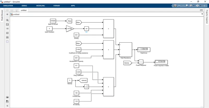
The constants blocks are used for mass,velocity,gravity,airdrag coefficient,air density,frontal area.
The product blocks are used to perform the formulas for rolling resistance force and aerodynamic force and all others...
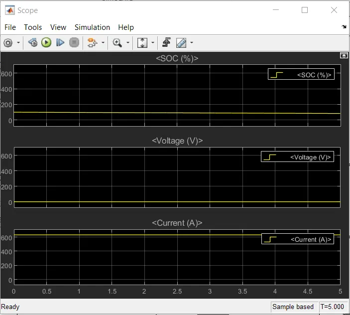
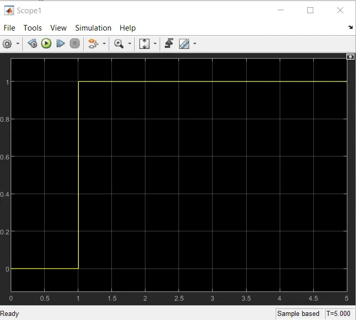
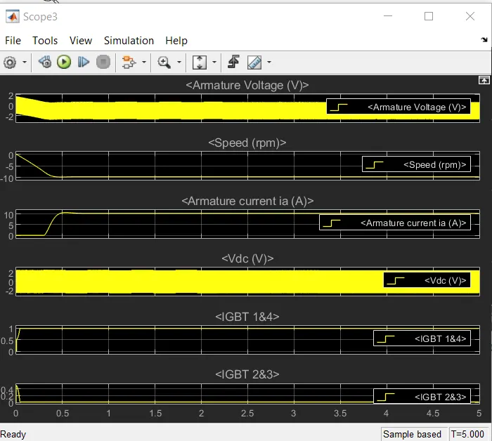
7. A. Design an electric powertrain with type of motor, it’s power rating, and energy requirement to fulfill aircraft towing application in Simulink. Estimate the duty cycle range to control the aircraft speed from zero to highest. Make all required assumptions. Prepare a table of assumed parameters. Draw a block diagram of powertrain.
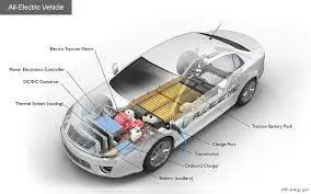
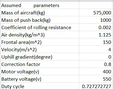
Assumed Parameter.
Mass of aircraft 575000kg
Mass of the pushback truck 1000kg
Coefficient of rolling resistance 0.002
Air density 1.125kg/m^3
Frontal area 150m^2
Velocity 4m/s
Uphill gradient 0degree
Battery voltage 550V
Correction factor 0.8
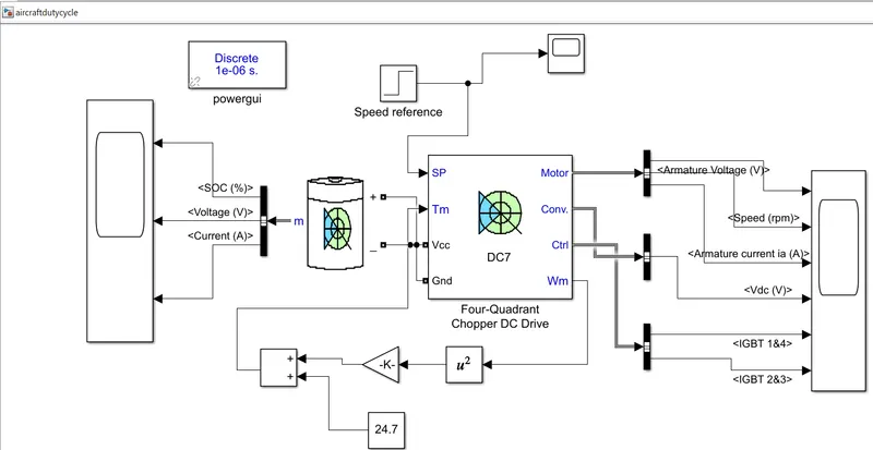
B. Also, Design the parameters in excel sheet.
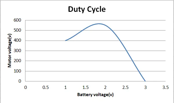
Conclusion:
Since we have seen for the graph of duty cycle.