Week-7 Challenge: DC Motor Control
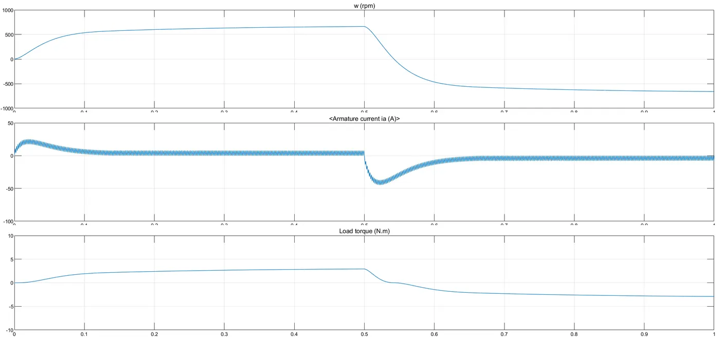
1) The armature current shoots up because of fast switching when the motor changes direction, and therefore, a high voltage (due to back emf) and current.
This can be negated by reducing the width of the pulse. As the width of the pulse is reduced, this means the duty cycle is reduced, and therefore - a lower voltage is drawn from the battery.
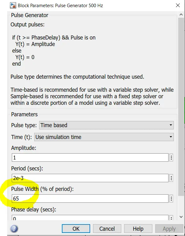
2) In the H-Bridge, speed control is achieved using a Bipolar junction transistor. There are four diodes, Q1-Q4 that are controlled using a switch block and a pulse modulated signal to control the duty cycle. By changing the width of the pulse, the time for which the transistors are open changes, and hence the terminal voltage to the motor changes. In this manner, speed control is achieved. However, the duty cycle must be changed manually by changing the pulse width - in other words, there is not closed-loop control of the duty cycle. This is an open-loop model. This is a continuous-time model as well.
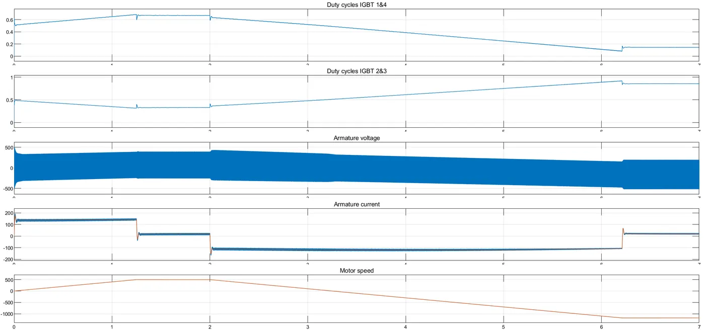
The 4 quadrant chopper, is a closed-loop model. The loop outputs the reference and commanded armature current signals, for the required torque. This is compared with the necessary duty cycle with a sawtooth carrier signal to obtain the required PWM signals for the chopper. In other words, there is automatic control of the duty cycle. The duty cycle changes automatically with the required torque and speed since it is a closed-loop model. This model works in the discrete-time domain.
Now, the armature current does not shoot up as much, previously it went past -50A.
3) Here, the vehicle speed-torque characteristics are implemented instead of a constant load.
Tv = 0.0051W^2 + 24.7
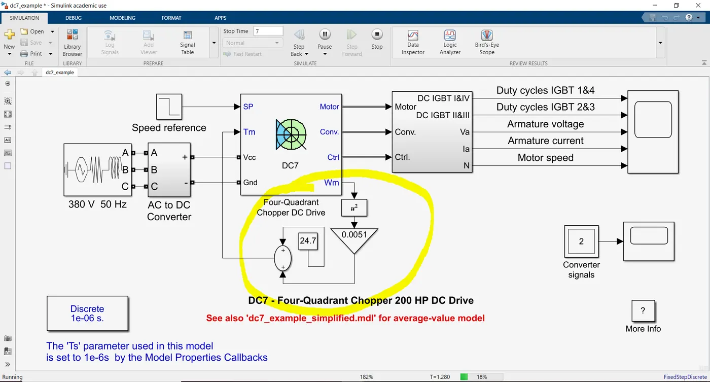
Here are the outputs after implementing a vehicle model as a load.