Week-7 Challenge: DC Motor Control
1. A. Explain a MATLAB demo model named ‘Speed control of a DC motor using BJT H-bridge’.
B. Comment on the armature current shoot-up from the scope results.
C. Refer to the help section of ‘The Four-Quadrant Chopper DC Drive (DC7) block’. Compare it with the H-bridge model.
Ans:
A)
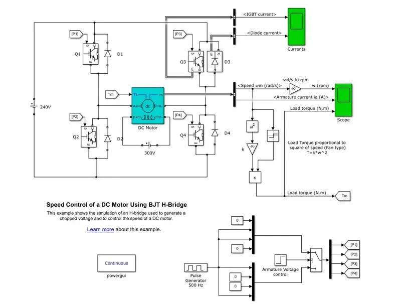
- In this model H bridge is designed to control speed of dc motor
- Four IGBT switches are used for voltage terminal reversal across the motor
- Gate terminal of IGBT are controlled by pulses generated bu a pulse generator
- Armature voltage control is a step signal with steo time 0.5 and final value 1
- D1 and D4 work as a pair and D2 and D3 work as a pair, When D1and D4 conducts armature terminal of motor A+ connected to +ve terminal of input volage source and A- connected -ve terminal of input voltage source,When D2D3 pair conducted the A+ terminal of motor connected to negative terminal of voltage source and A- terminal connected to positive terminal of voltage sources,So the direction of the dc motor changes accordingly
- The motor strats in positive direction with 75% duty cycle given in pulse generator
- At t=0.5sec The armature voltage polarity changes and motor runs in opposite direction
- The load torque is given as mechanical input to the motor
- Stop time =1s and after running the program we got the output as shown below
OUTPUT
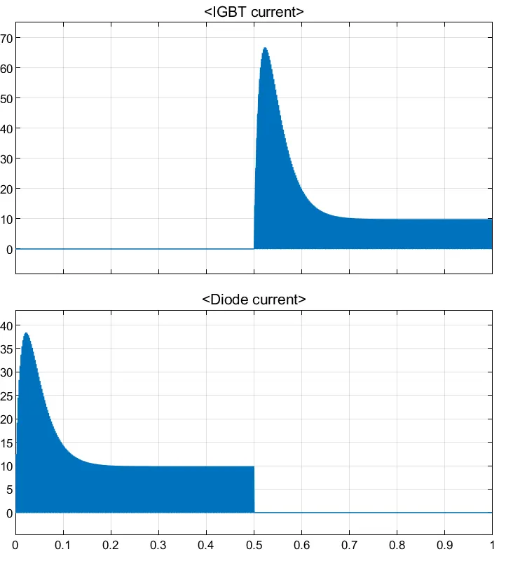
- From above plot it is undestood that till 0.5 sec diode is conducting and after 0.5sec diode current become zero.after 0.5sec IGBT current is present.
Obsevations:
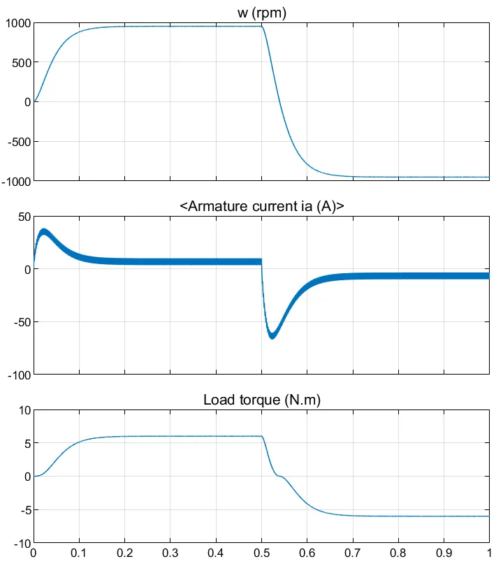
- Speed of the motor increases from 0 to 950rpmup to 0.5secie forward motoring action
- Then speed reduces to 0 during dynamic forward breaking
- after that speed value falls from 0 to -950 so reverse motoring action take place up to 1sec
- After 0.5sec The armature current direction reversed, Speed curve goes to negative direction which means motor is rotating in opposite direction alse load torque reduces to negative value as shown.
- Initially torque increases from 0 to 0.5sec during forward motoring action
- then during forwarddynamic breaking torque value reduces to zero
- After that up to 1 sec torque increases in reverse direction
B)
- Armature current has sudden rise When the motor starts during starting time high voltage is suddenly applied to the motor terminals,so the starting current of dc motor has high value because no back emf is present at the time of starting.
- Similarly armature current has sudden fall after 0.05 sec Because volatage polarity of armature terminal reversed and current starts to flow in reverse direction and motor starts rotates in reverse direction.
- The voltage applied across armature terminal is very high
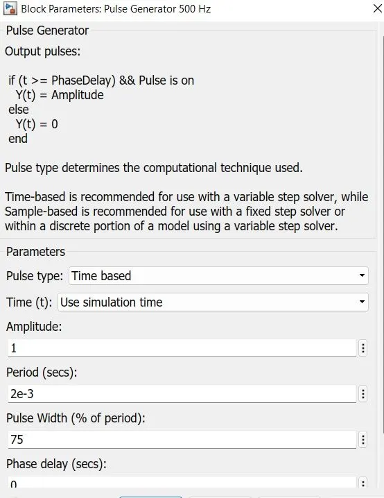
- Pulse width 75%
- so applied voltage=280*75/100
=180V
So high voltage at the starting and high reverse voltage after 0.5sec causes the armature current shootup .we can reduce it with adjusting duty cycle
C)We open the DC7four quadrant chopper 200HP dc drive and run the mode and observed the output and compared it with the Hbridhe and following observations are made
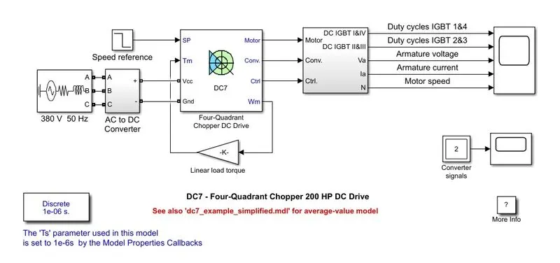
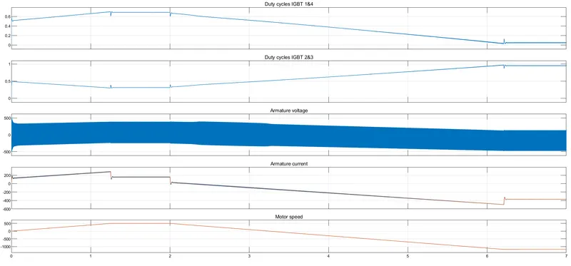
- Four quadrant chopper can operates in all modes but H bridge can operates only 2 mode
- In 4 quadrant chopper regenerative braking is possible but in H bridge its not possible
- Four quadrant chopper has better efficiency than H bridge
- In DC7 chopper model speed controlled by varying currrent pulses and in H bridge model breaking is done by changing polarity of armature voltage terminals
- Simulation is continuous in H bridge and simulation is discrete in 4quadrant chopper
2. Develop a 2-quadrant chopper using simulink & explain the working of the same with the relevant results. (Refer to article - Multiquadrant operation of motor )
ans:
Developed a two quadrant chopper using simulink as shown below
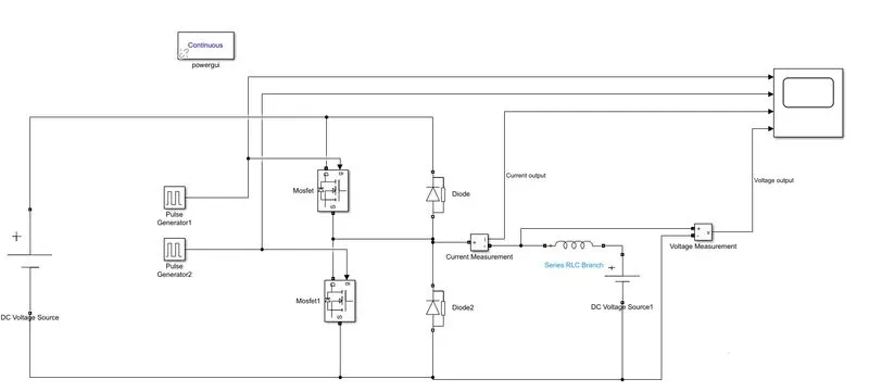
Block Used:DC voltage source,pulse generator,Mosfet,Current measurement and Voltage measurement,diode,powergui,Inductor,and scope for viewing the results
Procedure:
- We use DC voltage source for input and set the voltage value 25V
- Pulse generators used for giving input to the Mosfet gate,We used 2 pulse generetors
For pulse generator 1 we gave Pulse amplitude=25,Period=0.02,Pulse width=50% and phase delay=0
For pulse generator 2 we gave Pulse amplitude=25,Period=0.02,Pulse width=50% and phase delay=0.01
We gave phase delay to second pulse generator because diodes shouldnt operate at the same
- We connected Inductance in series in the load side of value 1mH and a dc voltage source with V=12
- Then stop time set to 0.5seconds
Output:
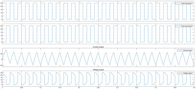
Working of 2quadrant chopper:
- When diode 2 conduct or mosfet 1 is on,load voltage is equal to input voltage=25V during on time
- When diode1 is conduct or mosfet2 is on output voltage =0
- Load current is assumed negative at t=0.It changes from negative to positive positive during on state and from positive to nrgative value during off state
- When voutput is positive and Ioutput is negative shows that diode2 conducts;When both voltage and current output are positive mosfet 1 conducts
- It is seen from the output waveform that Vout is always positive because diode 2 is a free wheeling diode, and current outputs had negative and positive value ,So when current and voltages are positive it is operated in first quadrant and when current output is negative and voltage output is positive it is operated in second quadrant
3. Explain in a brief about operation of BLDC motor.
Brushless DC electric motors also known as electronically commutated motors (ECMs, EC motors). Primary efficiency is a most importAnt feature for BLDC motors. Because the rotor is the sole bearer of the magnets and it doesn't require any power. i.e. no connections, no commutator and no brushes. In place of these, the motor employs control circuitry. To detect where the rotor is at certain times, BLDC motors employ along with controllers, rotary encoders or a Hall sensor.In this motor, the permanent magnets attach to the rotor. The current-carrying conductors or armature winding are located on the stator. They use electrical commutation to convert electrical energy into mechanical energy. The main design difference between a brushed and brushless motors is the replacement of mechanical commutator with an electric switch circuit. A BLDC Motor is a type of synchronous motor in the sense that the magnetic field generated by the stator and the rotor revolve at the same frequency.Brushless motor does not have any current carrying commuteters The field inside a brushless motor is switched through an amplifier which is triggered by the commutating device like an optical encoder.The layout of a DC brushless motor can vary depending on whether it is in outrunner style or inrunner style.Outrunner – The field magnet is a drum rotor which rotates around the stator. This style is preferred for applications that require high torque and where high rpm isn’t a requirement.In runner – The stator is a fixed drum in which the field magnet rotates. This motor is known for producing less torque than the out runner style, but is capable of spinning at very high rpm.
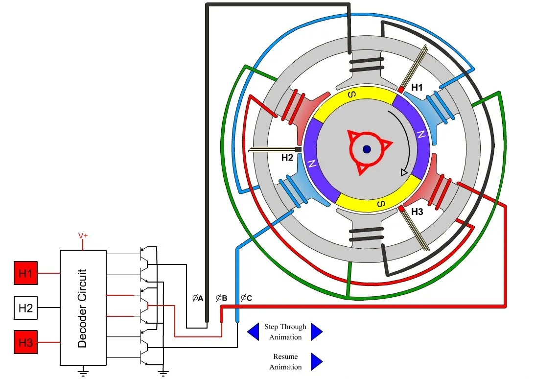
BLDC motor works on the principle similar to that of a brushed dc motor. The Lorentz force law which states that whenever a current carrying conductor placed in a magnetic field it experiences a force. As a consequence of reaction force, the magnet will experience an equal and opposite force. In the BLDC motor, the current carrying conductor is stationary and the permanent magnet is moving.When the stator coils are electrically switched by a supply source, it becomes electromagnet and starts producing the uniform field in the air gap. Though the source of supply is DC, switching makes to generate an AC voltage waveform with trapezoidal shape. Due to the force of interaction between electromagnet stator and permanent magnet rotor, the rotor continues to rotate.
ADVANTAGES:Less overall maintenance due to absence of brusheSReduced size with far superior thermal characteristicsHigher speed range and lower electric noise generation.It has no mechanical commutator and associated problemsHigh efficiency and high output power to size ratio due to the use of permanent magnet rotorHigh speed of operation even in loaded and unloaded conditions due to the absence of brushes that limits the speedSmaller motor geometry and lighter in weight than both brushed type DC and induction AC motors.Long life as no inspection and maintenance is required for commutator systemHigher dynamic response due to low inertia and carrying windings in the statorLess electromagnetic interferenceLow noise due to absence of brushes
LIMITATION:These motors are costlyElectronic controller required control this motor is expensiveREquires complex drive circuitryNeed of additional sensors