Week -2
- Make a Simulink model of Doorbell using solenoid block with the following details:
In the above arrangement, when the switch is closed the electromagnet receives electrical power from the battery and pulls the metal arm to hit the bell producing sound.
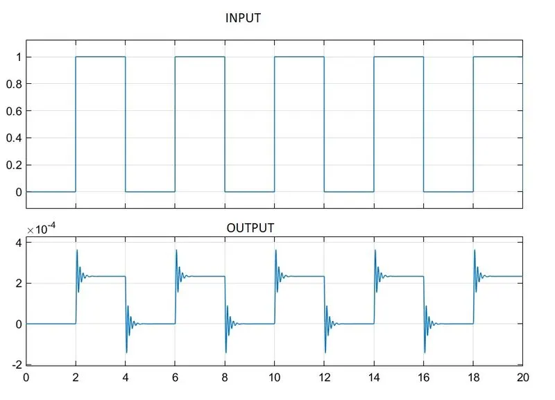
Create a situation where the switch is closed for 2 seconds and then released. Observe the physical movement of the plunger.
Assume remaining parameters.
Answer.
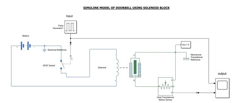
Simulink model of doorbell using solenoid block Shown above.
Block used: Pulse generator,simulink-ps converter,battery,spst switch,electrical reference,solenoid block,ideal translational motion senser, solver configuaration,mechanical translation reference and scope.
PROCEDURE :Here we use pulse generator as input block.Pulse amplitude is set to 1 ,period is set to 2sec and phase is delayed by 1 to get the require input.The output from pulse generator given to SPST switch
through a simulink-ps converter.This switch controls the current flow through solenoid .Battery is used as voltage source for solenoid.Electrical reference is connected as shown above.Afterevery 2sec switch is
closed for 2sec and current flows through solenoid,this cause movements in plunger .Here we used Ideal translation motion senser to sense the movements of plunger.Mechanical translation reference and solver
configuaration connected as shown above.Output is taken from position port of the sensor and given to scope through ps-simulink converter.Stop time is set to 20sec.
OUTPUT:From the plot shown below we can see that after every 2sec displacement in plunger position for 2sec.ie bell rung for 2sec.
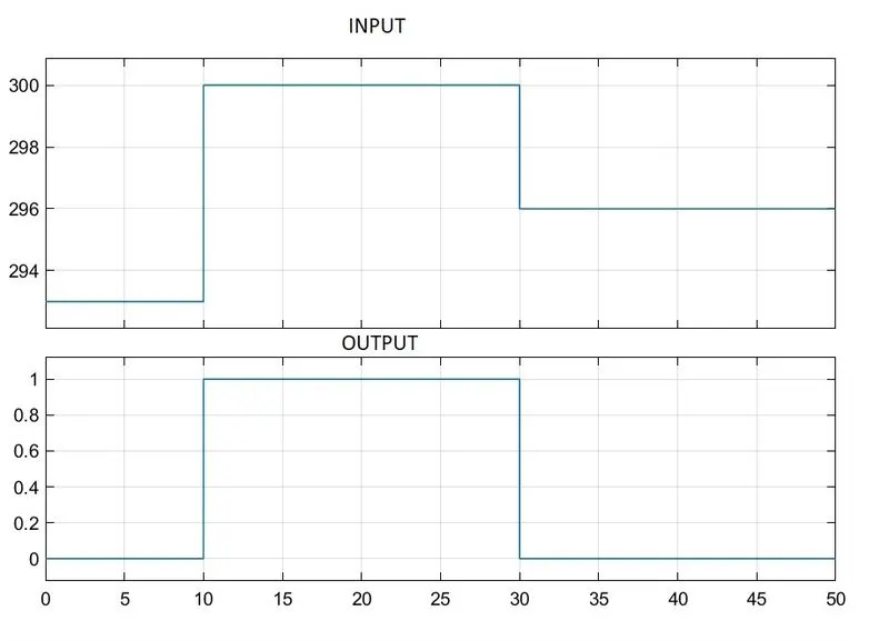
2. Use a thermistor to sense the temperature of a heater & turn on or turn off the fan as per the below conditions:
Temperature source: 20 °C from 0 to 10 seconds, 27 °C from 10 to 30 seconds, 23 °C from 30 to 50 seconds
Fan conditions: ON if the temperature above 25 °C, OFF otherwise
ANSWER:
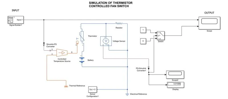
Simulink model of thermistor controlled fan switch is shown above.
Block used:Signal builder, simulink-ps converter,controlled temperature source,thermal reference, battery,thermistor,resistor, voltage senser,electrical reference,solver configuaration,ps-simulink
converter,scope,dislay and switch.
PROCEDURE:Blocks are connected as shown above and stop time set to 50sec.First we use constant block of value 298 instead of signal builder to get threshold value for switch and run the simulink we get
voltage ou in scope and display ie.0.01099 and given this value to switch threshold,and deleted the constant block and connected the signal builder.Then run the simulink and we got the output as shown below
OUTPUT: From the below plot we can observe that switch is on when input is greater than 298k(25C)