Week-7 Challenge: DC Motor Control
1.
A. Explain a MATLAB demo model named ‘Speed control of a DC motor using BJT H-bridge’.
B. Comment on the armature current shoot-up from the scope results.
C. Refer to the help section of ‘The Four-Quadrant Chopper DC Drive (DC7) block’. Compare it with the H-bridge model.
A.Speed control of a DC motor using BJT H-bridge
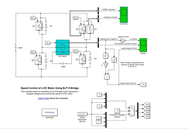
- A Bipolar Junction Transistor (BJT) operates as an IGBT when it is used for power power switching application.
- When the BJT is conducting, a forward voltage will be Vfwill be generated between collector and emitter. Therefore, IGBT block can be used to model the BJT device.
- The input given is a DC voltage source of 240V.
- The motor preset model is 5HP, 240V,1750RPM,Field:300V.
- The armature mean voltage can be varied from 0 to240V when the duty cycle is varied from 0 to 100%.
- H bridge consists of 4 BJT and diode pairs. Two transistors are switched simultaneously:Q1 and Q4, Q2 and Q3.
- When Q1 and Q4 are fired, a positive voltage is applied to the motor and diodes D2-D3 operates as free wheeling diodes when Q1 and Q4 are switched OFF.
- When Q2 and Q3 are fired, a negative coltage is applied to the motor and the diodes D1 and D4 will operates as free wheeling diodes when Q2 and Q3 are switched OFF.
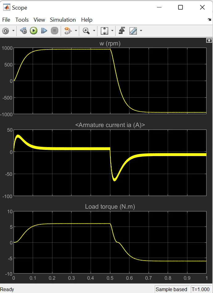
B) When the simulation is run with the default parameters with the pulse width (duty cycle) as 75%. The output obtained is
The diode and IGBT current is
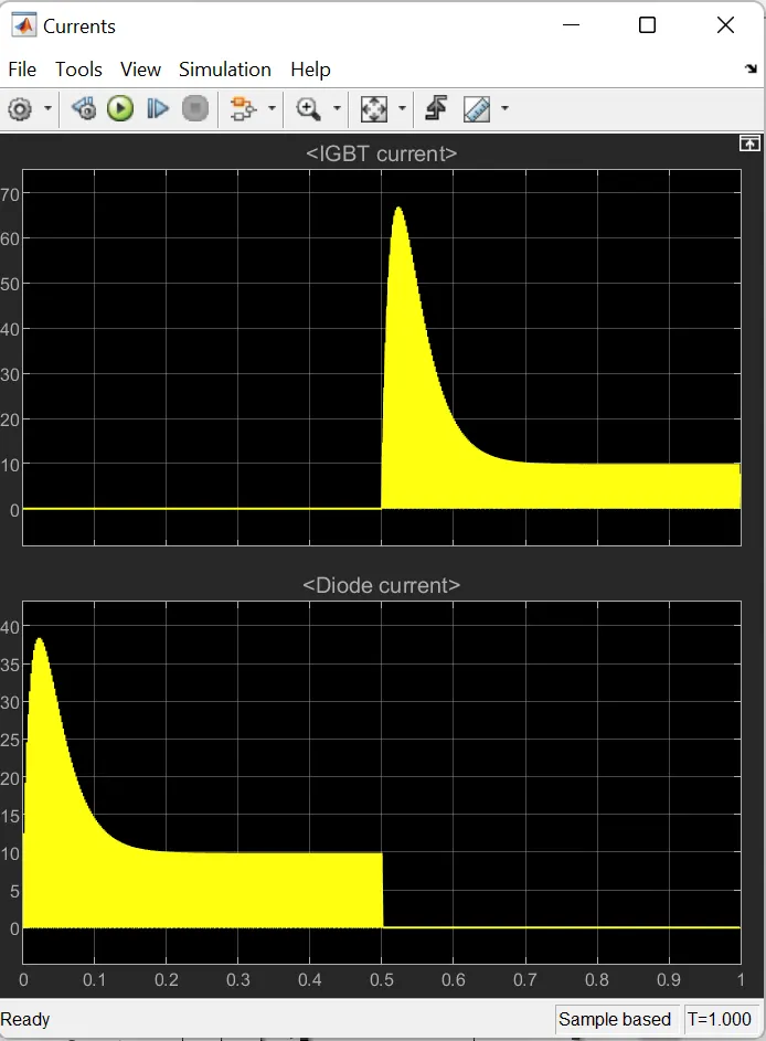
It is evident that after t=0.5 sec the armature voltage has reversed and motor runs in negative direction.
When the duty cycle was changed to 45% the output obtained is
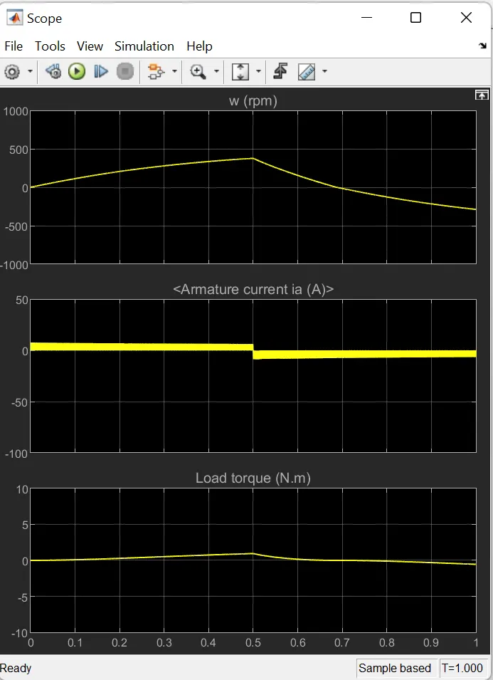
The value of the current shootup has decreased and has a smooth current flow.
The scope is showing the motor speed, armature current and load torque and currents flowing in BJT Q3 and diode D3.
C)The four quadrant chopper DC drive(DC&) block.
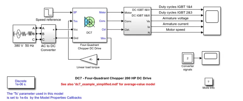
The block diagram is of a four quadrant chopper 200 HP DC drive which is seperately excited with a constant 150 V DC field voltage source.
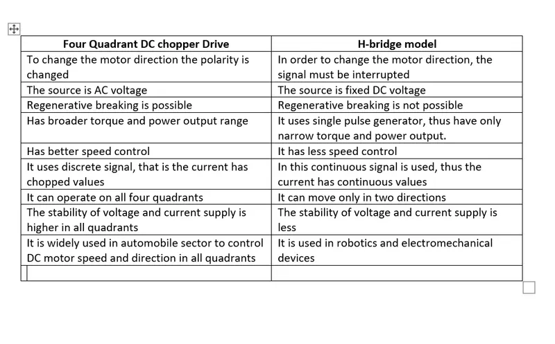
The comparison of four quadrant DC chopper drive and H bridge model
2. Develop a 2-quadrant chopper using simulink & explain the working of the same with the relevant results.
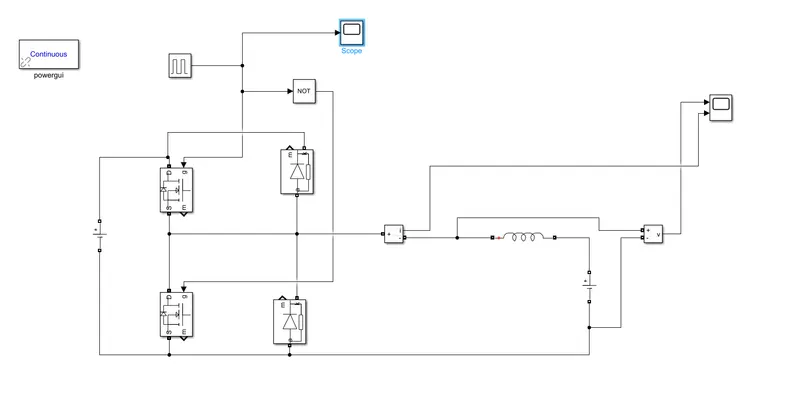
The blocks used for the simulation are mosfets, diodes, not gate, pulse generator, powergui, series L load, voltage and current measurement, dc power supply and scope.
The dc voltage source of 24v is connected.
The load voltage is 12v.
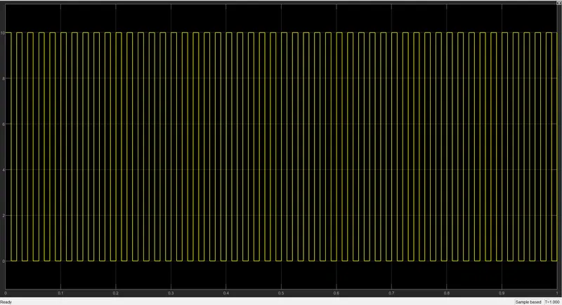
The pulse generator is connected to the mosfet 1 and the mosfet 2 is connected to the pulse generator through a not gate.
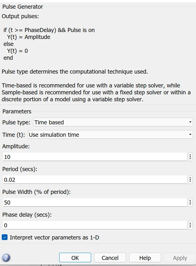
The input from the pulse generator is
The output current and voltage obtained
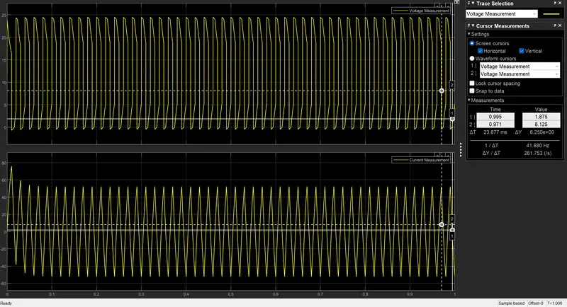
The output of the current waveform is in the positive direction and the voltage waveform is in the positive and negative half cycle.
https://drive.google.com/file/d/1c54jIzu6n7IUQLb22V8W1ZN7TSzW905R/view?usp=drivesdk
3. Brushless DC motor
It is also called as electronically commutated motors.
In this motor the rotor is a permanent magnet so there is no need for brushes for exciting the rotor.
It is an elecronically commutated dc motor which doesnot have brushes.
It is highly efficient in producing large amount of torque over a vast speed range.
Rotor is permanent magnet and this rotates around the fixed armature and overcome the problem of connecting current to the armature.
They have smooth operation.
They doesnot have any current carrying commutators. The field inside the commutator is switched through an amplifier which is triggered by the commutating device like an optical encoder.
Layout depends on whether it is "out runner style', or "inrunner style".
-Out runner style- The field magnet is a drum rotor which rotates around the stator. It is preferred foe applications that require high torgue and where high rpm is not required.
-In runner style- The stator is a fixed drum in which the field magnet rotates. It produces less torque than out runner style but is capable of spinning at very high rpm.
WORKING PRINCIPLE
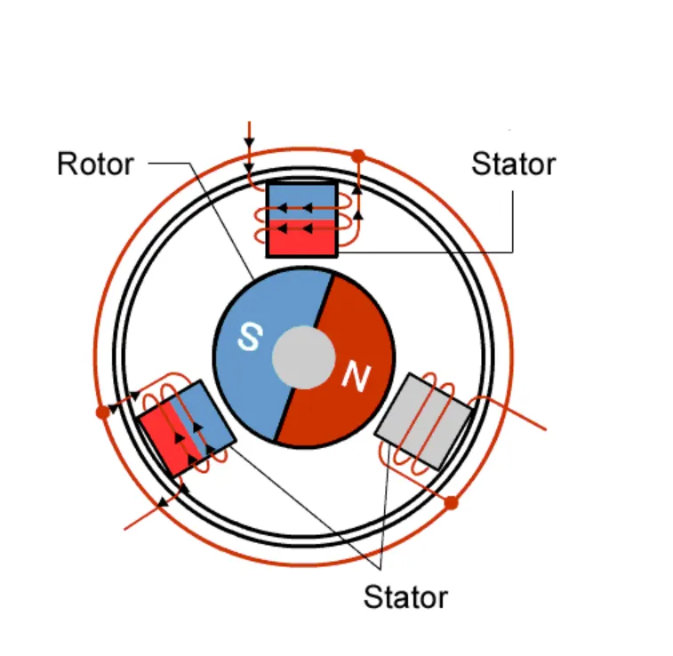
Current carrying conductor is stationary and the permanent magnet is moving. When the stator coil gets supply from source, it becomes electromagnet and starts producing the uniform magnetic field in the air gap. Though the source of supply is DC, switching makes to generate an AC voltage waveform with trapezoidal shape. Due to the force of interaction between electromagnetic stator and permanent rotor, the rotor continues to rotate.
ADVANTAGES OF BRUSHLESS DC MOTOR
There is no brushes so low maintenance.
Reduced size with far superior thermal characteristics.
High speed range and low electric noise generation.
It has no mechanical commutators and associated problems.
High efficiency and high output to power ratio due to use of permanent magnet.
High speed of operation even in loaded and unloaded conditions due to the absense of brushes that limits the speed.
Small motor geometry adn light weight
LIMITATIONS
High cost
Electronic controller required to control this motor is expensive.
Requires complex drive circuitry
Need additional sensors
APPLICATIONS
Computer hard drives and DVD/CD players
Used in car parts and wheel coupler from the battery
Electric and hybrid electric vehicles.
Industrial robots, CNC machine tools and simple belt driven system. etc