Week-7 Challenge: DC Motor Control
1. A. Explain a MATLAB demo model named ‘Speed control of a DC motor using BJT H-bridge’.
B. Comment on the armature current shoot-up from the scope results.
C. Refer to the help section of ‘The Four-Quadrant Chopper DC Drive (DC7) block’. Compare it with the H-bridge model.
A.MATLAB demo model named ‘Speed control of a DC motor using BJT H-bridge.
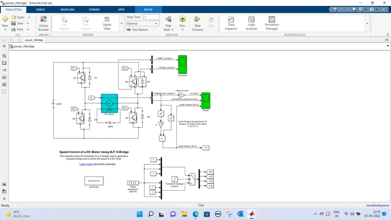
BJT-H bridge is a simple circuit that lets you control the DC motors,H like configuration with four switching elements with load at centre
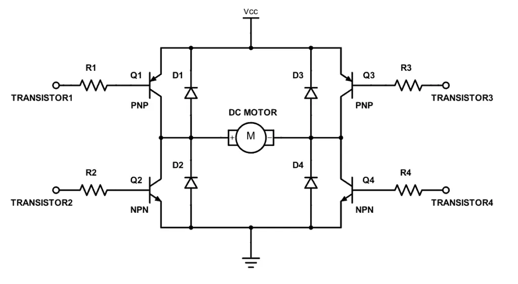
switching elements (Q1to Q4)usually Bi polar junction transistors some high applications will have IGBT
Diodes(D1to D4) are catch diodes they are schotty type
Forward motoring ,when Q1 & Q2 are triggered by a positive voltage applied to motor & diodes D2 & D3 operates as free-wheeling diodes.
Reverse motoring,when Q2 & Q3 are triggered by negative voltage applied to motors & diodes D1 & D4 operates as free wheeling diodes.
Simulation model & results are
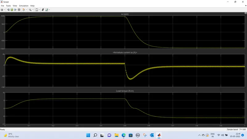
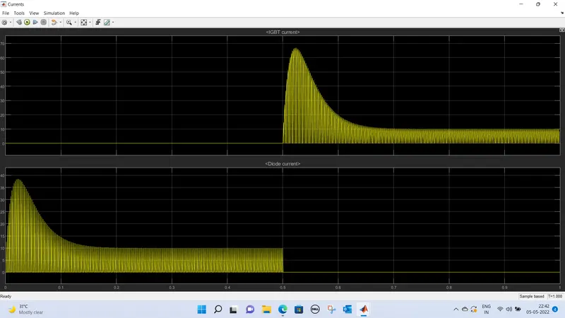
B.Armature current shoot-up from the scope results
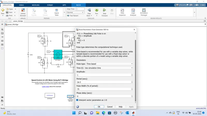
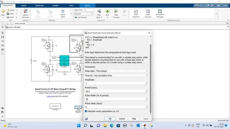
Changing the pulse width 75% to 40%
results
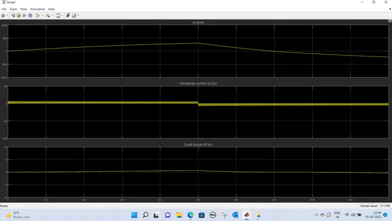
armature current spike reduced by changing the duty cycle from 75% to 40%.
C. Refer to the help section of ‘The Four-Quadrant Chopper DC Drive (DC7) block’. Compare it with the H-bridge model
Four-quadrant chopper DC drive(DC7)block represents a four quadrant,DC supplied chopper drive for DC motors,this drive features closed loop speed control with four-quadrant operation,speed control loopoutputs refrence armature current of machine
Using the PI controller chopper duty cycle works to armature current,machine is sepratedly excited with a constant DC field voltage source,thus no field voltage voltage control by default,the current is set its steady state value when simulation started,
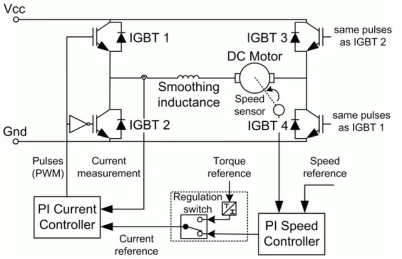
working of four quadrant chopper
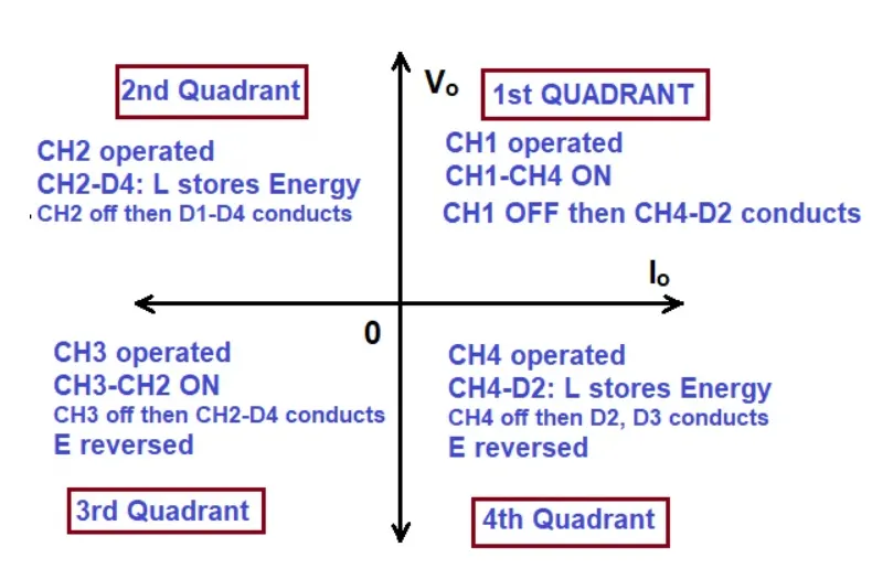
Diffrence between the H-bridge & DC7 block
In H-bridge we need to reverse the polarity of current in order to change the rotation of the motor where asDC7 block uses the refrence speed to change the direction of rotation,due to back emf,current shoot up disturbances are high in H-bridge,it operates only in two modes include forward motoring & reverse motoring where as in DC7 will work in four operating conditions are forward motoring,forward braking reverse motoring reverse braking.
2. Develop a 2-quadrant chopper using simulink & explain the working of the same with the relevant results.
Type -C chopper or Two-quadrant type-A Chopper
Type C chopper is obtained by connecting type –A and type –B choppers in parallel. We will always get a positive output voltage V0 as the freewheeling diode FD is present across the load. When the chopper is on the freewheeling diode starts conducting and the output voltage v0 will be equal to Vs . The direction of the load current i0 will be reversed. The current i0 will be flowing towards the source and it will be positive regardless the chopper is on or the FD conducts. The load current will be negative if the chopper is or the diode D2 conducts. We can say the chopper and FD operate together as type-A chopper in first quadrant. In the second quadrant, the chopper and D2 will operate together as type –B chopper.
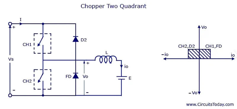
The average voltage will be always positive but the average load current might be positive or negative. The power flow may be life the first quadrant operation ie from source to load or from load to source like the second quadrant operation. The two choppers should not be turned on simultaneously as the combined action my cause a short circuit in supply lines. For regenerative braking and motoring these type of chopper configuration is used.
Type D Chopper or Two-Quadrant Type –B Chopper
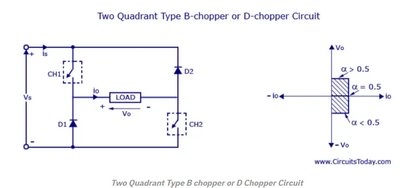
The circuit diagram of the type D chopper is shown in the above figure. When the two choppers are on the output voltage v0 will be equal to Vs . When v0 = – Vs the two choppers will be off but both the diodes D1 and D2 will start conducting. V0 the average output voltage will be positive when the choppers turn-on the time Ton will be more than the turn off time Toff its shown in the wave form below. As the diodes and choppers conduct current only in one direction the direction of load current will be always positive.

The power flows from source to load as the average values of both v0 and i0 is positive. From the wave form it is seen that the average value of V0 is positive thus the forth quadrant operation of type D chopper is obtained.
From the wave forms the Average value of output voltage is given by
V0= (Vs Ton-VsToff)/T = Vs.(Ton-Toff)/T
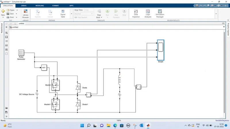
Tried the two-quadrant chopper using simulink
results
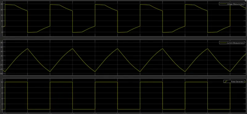
Taken two MOSFET blocks & diodesconnected as per circuit,DC voltage source given-24V,consider the LE load & DC voltage voltage sources connected in series with inductor,pulse genrator block is used to give gate pulses,NOT gate is used to avoid the closure two MOSFET at same time
Voltage waveform is not going less than zero.minimum voltage is zero & max value is in positive,current may be in poistive as well as negative.
3. Explain in a brief about operation of BLDC motor.
Brushless DC motors (BLDC) have been a much focused area for numerous motor manufacturers as these motors are increasingly the preferred choice in many applications, especially in the field of motor control technology. BLDC motors are superior to brushed DC motors in many ways, such as ability to operate at high speeds, high efficiency, and better heat dissipation.
They are an indispensable part of modern drive technology, most commonly employed for actuating drives, machine tools, electric propulsion, robotics, computer peripherals and also for electrical power generation. With the development of sensorless technology besides digital control, these motors become so effective in terms of total system cost, size and reliability.
These types of motors are highly efficient in producing a large amount of torque over a vast speed range. In brushless motors, permanent magnets rotate around a fixed armature and overcome the problem of connecting current to the armature. Commutation with electronics has a large scope of capabilities and flexibility. They are known for smooth operation and holding torque when stationary.
Unlike conventional brushed type DC motor, wherein the brushes make the mechanical contact with commutator on the rotor so as to form an electric path between a DC electric source and rotor armature windings, BLDC motor employs electrical commutation with permanent magnet rotor and a stator with a sequence of coils. In this motor, permanent magnet (or field poles) rotates and current carrying conductors are fixed.
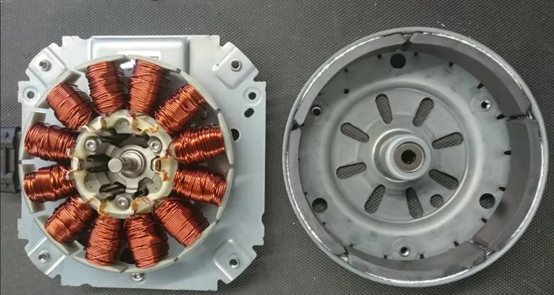
Construction of BLDC Motor
The construction of this motor has many similarities of three phase induction motor as well as conventional DC motor. This motor has stator and rotor parts as like all other motors.
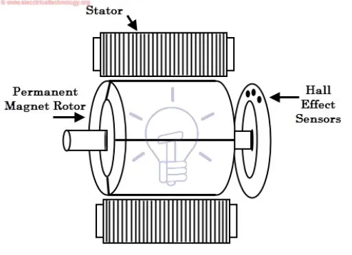
Stator of a BLDC motor made up of stacked steel laminations to carry the windings. These windings are placed in slots which are axially cut along the inner periphery of the stator. These windings can be arranged in either star or delta. However, most BLDC motors have three phase star connected stator.
Each winding is constructed with numerous interconnected coils, where one or more coils are placed in each slot. In order to form an even number of poles, each of these windings is distributed over the stator periphery.The stator must be chosen with the correct rating of the voltage depending on the power supply capability. For robotics, automotive and small actuating applications, 48 V or less voltage BLDC motors are preferred.
ROTOR
BLDC motor incorporates a permanent magnet in the rotor. The number of poles in the rotor can vary from 2 to 8 pole pairs with alternate south and north poles depending on the application requirement. In order to achieve maximum torque in the motor, the flux density of the material should be high. A proper magnetic material for the rotor is needed to produce required magnetic field density
Hall Sensors
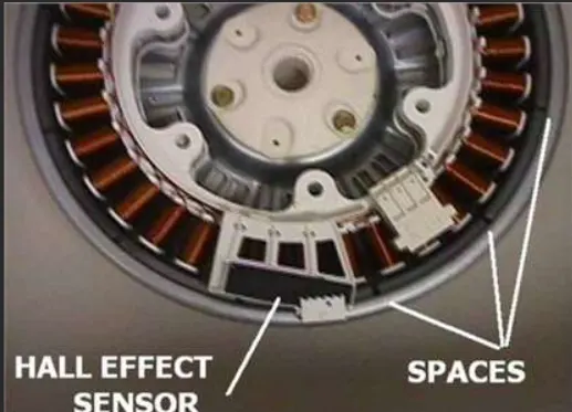
Hall sensor provides the information to synchronize stator armature excitation with rotor position. Since the commutation of BLDC motor is controlled electronically, the stator windings should be energized in sequence in order to rotate the motor. Before energizing a particular stator winding, acknowledgment of rotor position is necessary. So the Hall Effect sensor embedded in stator senses the rotor position.
Most BLDC motors incorporate three Hall sensors which are embedded into the stator. Each sensor generates Low and High signals whenever the rotor poles pass near to it. The exact commutation sequence to the stator winding can be determined based on the combination of these three sensor’s response.
Working Principle and Operation of BLDC Motor
BLDC motor works on the principle similar to that of a conventional DC motor, i.e., the Lorentz force law which states that whenever a current carrying conductor placed in a magnetic field it experiences a force. As a consequence of reaction force, the magnet will experience an equal and opposite force. In case BLDC motor, the current carrying conductor is stationary while the permanent magnet moves
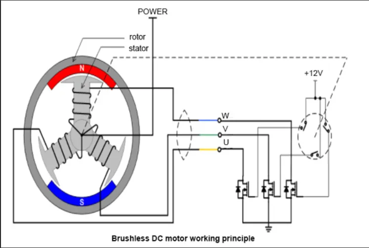
When the stator coils are electrically switched by a supply source, it becomes electromagnet and starts producing the uniform field in the air gap. Though the source of supply is DC, switching makes to generate an AC voltage waveform with trapezoidal shape. Due to the force of interaction between electromagnet stator and permanent magnet rotor, the rotor continues to rotate.
Consider the figure below in which motor stator is excited based on different switching states. With the switching of windings as High and Low signals, corresponding winding energized as North and South poles. The permanent magnet rotor with North and South poles align with stator poles causing motor to rotate.
Observe that motor produces torque because of the development of attraction forces (when North-South or South-North alignment) and repulsion forces (when North-North or South-South alignment). By this way motor moves in a clockwise direction.
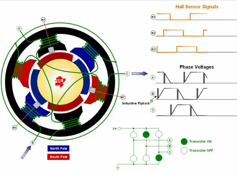
how we know which stator coil should be energized and when to do. This is because; the motor continuous rotation depends on the switching sequence around the coils. As discussed above that Hall sensors give shaft position feedback to the electronic controller unit.
Based on this signal from sensor, the controller decides particular coils to energize. Hall-effect sensors generate Low and High level signals whenever rotor poles pass near to it. These signals determine the position of the shaft.
Brushless DC Motor Drive
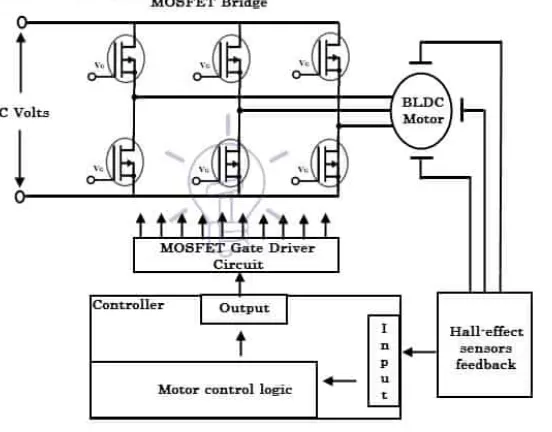
As described above that the electronic controller circuit energizes appropriate motor winding by turning transistor or other solid state switches to rotate the motor continuously. The figure below shows the simple BLDC motor drive circuit which consists of MOSFET bridge (also called as inverter bridge), electronic controller, hall effect sensor and BLDC motor.
Here, Hall-effect sensors are used for position and speed feedback. The electronic controller can be a microcontroller unit or microprocessor or DSP processor or FPGA unit or any other controller. This controller receives these signals, processes them and sends the control signals to the MOSFET driver circuit.
In addition to the switching for a rated speed of the motor, additional electronic circuitry changes the motor speed based on required application. These speed control units are generally implemented with PID controllers to have precise control. It is also possible to produce four-quadrant operation from the motor whilst maintaining good efficiency throughout the speed variations using modern drives.