Week-7 Challenge: DC Motor Control
Question 1a):
- BJT – Bipolar Junction Transistor
- IGBT – Insulated Gate Bipolar Transistor
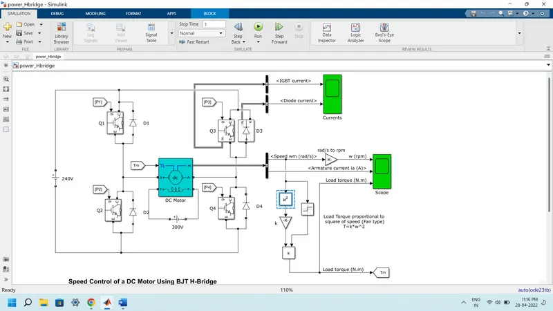
- H-bridge mainly operates in forward and reverse modes
- In general H-bridge operates in all the four quadrants of a model
- It is a low switching frequency used in matlab
- BJT and IGBT are switching state devices
- BJT has high switching speed
- MOSFET has major loads in it
- It has four switches Q1, Q2, Q2, Q4 and it is ready when the operation in it.
- Speed control of dc motor using BJT-H bridge
Question 1b):
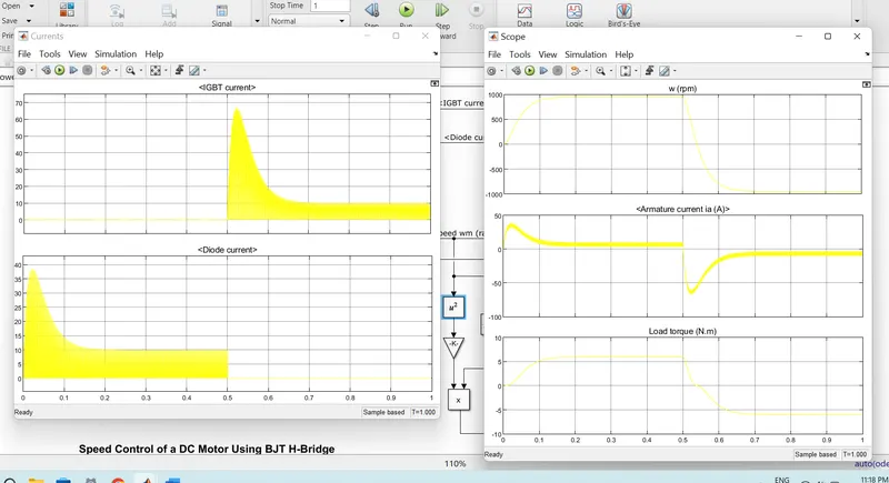
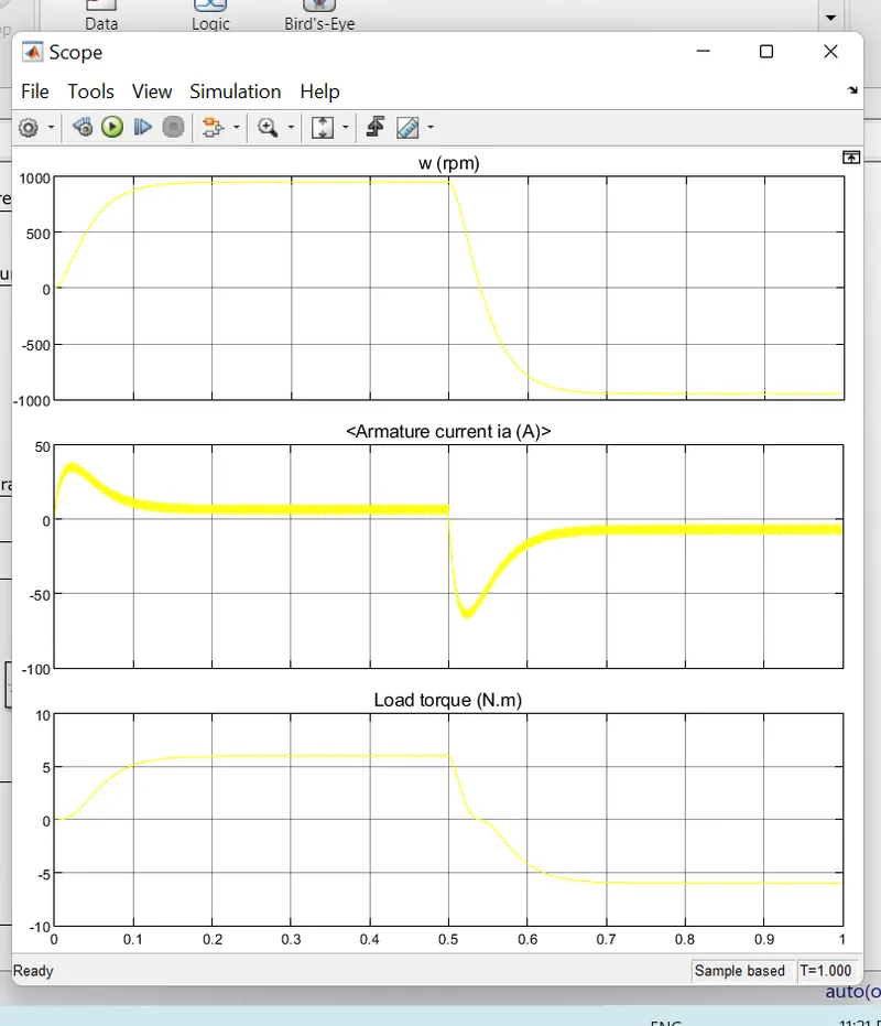
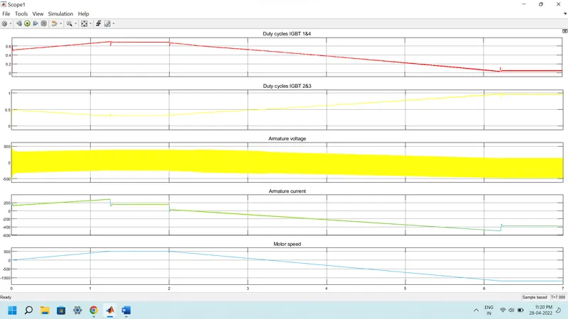
- The armature current (Ia) is on during the 1st transition and off during the 2nd transition
- It is controlled by the IGBT, BJT, diode in the circuit of the motors given
- In the 1st transition phase q1 and q4 are active
- And in 2nd transition phase q3 and q4 are active
- It clearly shows that the armature current varies on the transition state caused by the motor
- When in conducting state the BJT operates in the saturated region where the forward voltage is developed between emitter and the collector
- IGBT does not simulate the gate current controlling the BJT and it is controlled by Simulink
- The transistors are switched simultaneously
Question 1c):
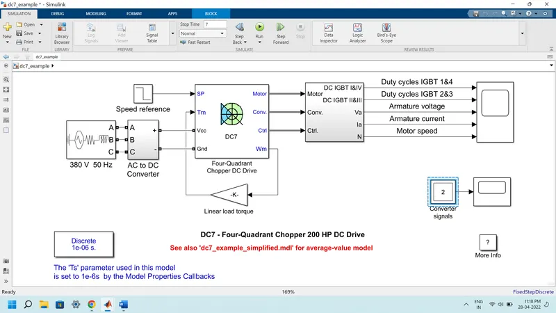
- The four quadrant DC7 chopper is explained in the above model
- 222 HP dc motor is excited with a constant 50V dc voltage source
- Armature voltage is given by IGBT converter controlled by two PI regulators
- Converter is fed by 515V dc bus by the rectification of 380V ac 50 Hz voltage source
- To limit the dc bus voltage during dynamic braking mode or braking chopper is added in the rectifier
- Speed regulator outputs the armature current
- The current controller in order to obtain electromagnetic torque to reach the desired speed
- Acceleration and deceleration are used to avoid the over armature current
- The IGBT 2 and 3 are opposite to 1 and 4
- Four quadrant chopper has higher switching frequency than h bridge
- Armature current variation is high in four quadrant than in h bridge
- H bridge are small electronics application and chopper is used for industry
Question 3:
Explanation:
- BLDC – brushless dc motor
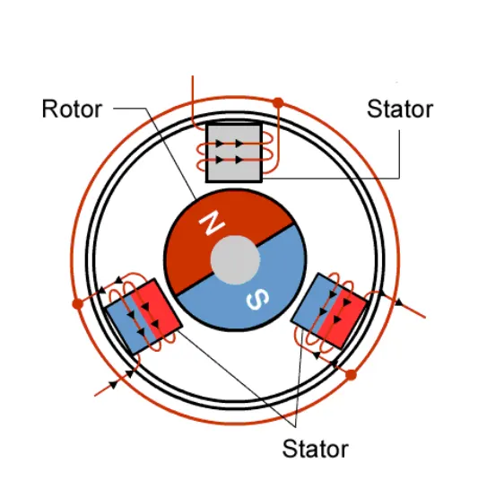
- It uses permanent magnet synchronous electric motor driven by dc current
- The commutation is controlled by electric commutation method
- It does not have brushes it has a mechanical contact with the commutator
- Electric path between source and rotor employs electric commutation by permanent magnet rotor and a stator coil
- The magnet with the poles rotates and the conductors which carries current are fixed
- Coils are switched electronically by the SCR
- Electronic commutation wipe out the commutator arrangement and brushes in dc motor
- Conventional method is a brushed dc motor
- The brushed dc motor have wear and tear in the circuit
- Heat is low when compared to brushed dc motor
- Efficiency of BLDC is high
- It do not undergo wear and tear of brushes because there is no brushes in it
- Noise is less as of brushed dc motor
- Motor cost is too high
- Permanent magnet in the motors can be demagnetized by mmf and high temperature
Refernce:https://www.renesas.com/us/en/support/engineer-school/brushless-dc-motor-01-overview
Conclusion:
All the theory with demo model is explained.