Week-7 Challenge: DC Motor Control
1.
a.
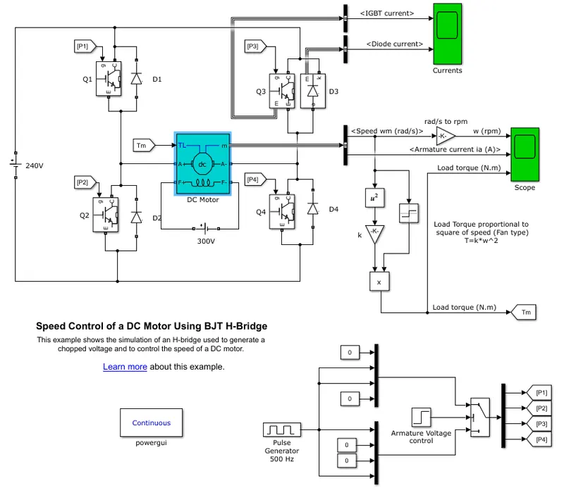
Fig speed control of a DC motor using BJT
DC motor is using parent modol 5HP , 240V, 1750RPM, And BJT are used to crate H bridge to control the Motor, simulink module uses signal 1/0 to control,
In the above modol pulse generatoe is used to generate diffarent frequencies and that is fed to mux and to swith which is connected with Armature Voltage control, here based on the freqency generated from Pulse generator armature voltage can be varied from 0 to 240V . out put of the swith is connected to 4 switches which form H brides ,The H-bridge consists of four BJT/Diode pairs (BJT simulated by IGBT models). Two transistors are switched simultaneously: Q1 and Q4 or Q2 and Q3. When Q1 and Q4 are fired, a positive voltage is applied to the motor and diodes D2-D3 operate as free-wheeling diodes when Q1 and Q4 are switched off. When Q2 and Q3 are fired, a negative voltage is applied to the motor and diodes D1-D4 operate as free-wheeling diodes when Q2 and Q3 are switched off.
b.
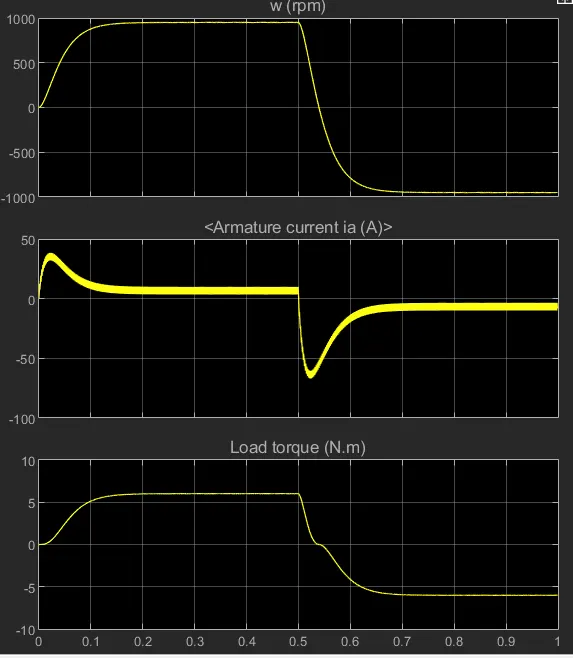
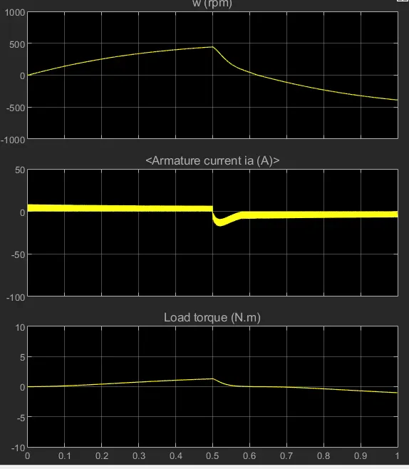
Fig:armature current with 75% duty cycle. fig: armature current with 50%duty cycle
- looking at the fig we can say that armature current initial shoot up smoothens after some time and as duty cycle re reduced current does not shootup and gives very smooth out put
- This shootup is due to swiching in the cicruit that causes heat loses to keep this kind of losses in check we have heat sinks .
c. The 200 HP DC motor is separately excited with a constant 150 V DC field voltage source. The armature voltage is provided by an IGBT converter controlled by two PI regulators. The converter is fed by a 515 V DC bus obtained by rectification of a 380 V AC 50 Hz voltage source. In order to limit the DC bus voltage during dynamic braking mode, a braking chopper has been added between the diode rectifier and the DC7 block.
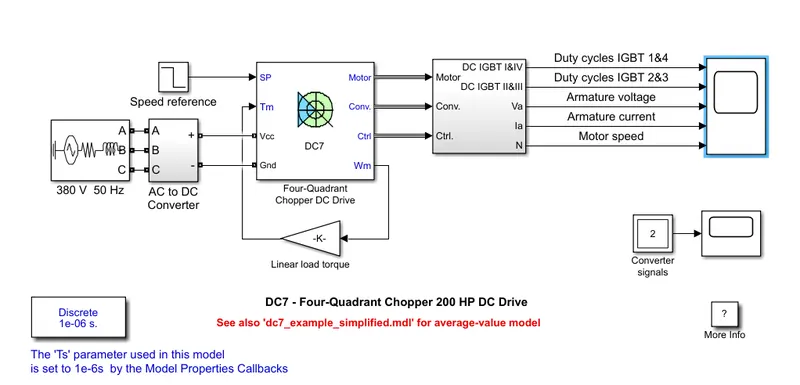
The first regulator is a speed regulator, followed by a current regulator. The speed regulator outputs the armature current reference (in p.u.) used by the current controller in order to obtain the electromagnetic torque needed to reach the desired speed,The current regulator controls the armature current by computing the appropriate duty ratios of the 5 kHz pulses of the four IGBT devices (Pulse Width Modulation).
comparison
| four quadrent chopper | H bridge |
| to reverse polarity needs to be change | to reverse IGBT contols needs to change |
| wide rage os torque and power | less range of torque and power due to signal generator |
| current has chopped value | current has continues value |
2.
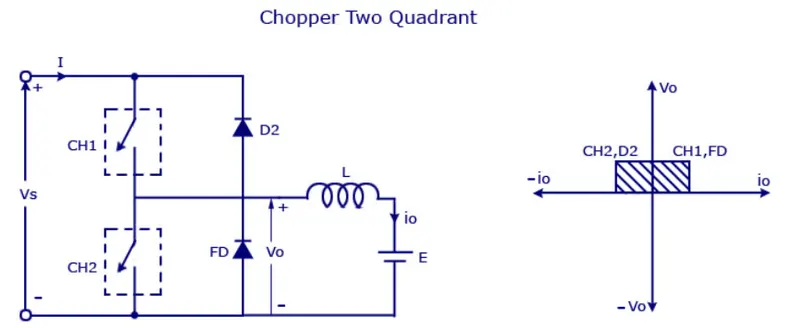
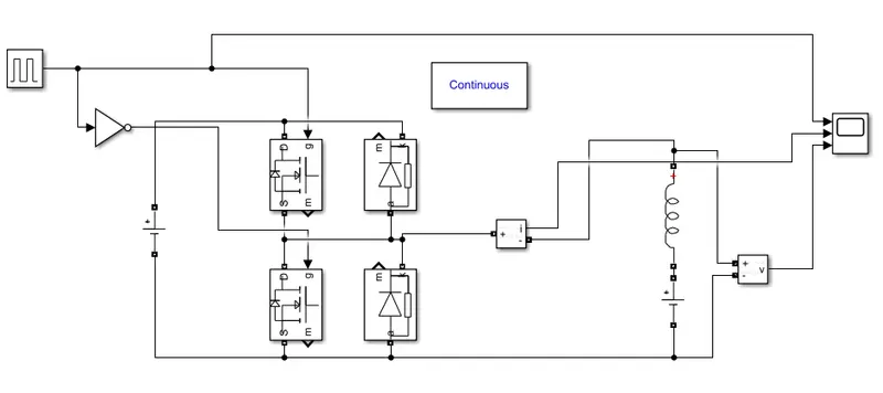
fig 2 quadrent chopper
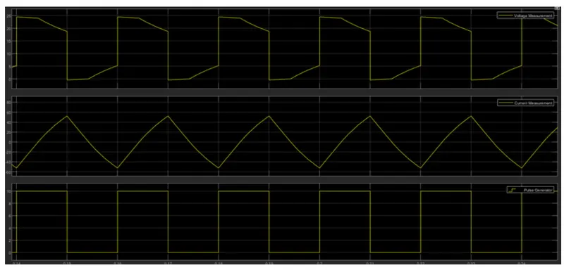
Two quadrent chopper or Type C chopper is obtained by connecting type –A and type –B choppers in parallel. We will always get a positive output voltage V0 as the freewheeling diode FD is present across the load. When the chopper is on the freewheeling diode starts conducting and the output voltage v0 will be equal to Vs . The direction of the load current i0 will be reversed. The current i0 will be flowing towards the source and it will be positive regardless the chopper is on or the FD conducts. The load current will be negative if the chopper is or the diode D2 conducts. We can say the chopper and FD operate together as type-A chopper in first quadrant. In the second quadrant, the chopper and D2 will operate together as type –B chopper.
3.
A brushless DC electric motor (BLDC motor or BL motor), also known as an electronically commutated motor synchronous DC motor, is a synchronous motor using a direct current (DC) electric power supply. It uses an electronic controller to switch DC currents to the motor windings producing magnetic fields which effectively rotate in space and which the permanent magnet rotor follows. The controller adjusts the phase and amplitude of the DC current pulses to control the speed and torque of the motor
The advantages of a brushless motor over brushed motors are high power-to-weight ratio, high speed, nearly instantaneous control of speed (rpm) and torque, high efficiency, and low maintenance. Brushless motors find applications in such places as computer peripherals (disk drives, printers), hand-held power tools, and vehicles ranging from model aircraft to automobiles. In modern washing machines, brushless DC motors have allowed replacement of rubber belts and gearboxes by a direct-drive design
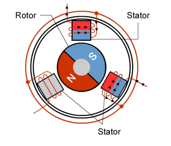
As their name implies, brushless DC motors do not use brushes. With brushed motors, the brushes deliver current through the commutator into the coils on the rotor. So how does a brushless motor pass current to the rotor coils? It doesn’t—because the coils are not located on the rotor. Instead, the rotor is a permanent magnet; the coils do not rotate, but are instead fixed in place on the stator. Because the coils do not move, there is no need for brushes and a commutator