Week-7 Challenge: DC Motor Control
Aim:
- To run the MATLAB demo script "Speed control of DC Motor using BJT H-Bridge" & evaluate the model such that Armature current dosen't shoot-up when the motor changes its direction of rotation.
- To compare 4 - Quadrant Chopper DC Drive (DC7) block with BJT H-bridge model.
- To build EV model using DC7 block.
INTRODUCTION:
Power Electronics:
Power Electronics is the application of solid - state electronics to the control and conversion of electric power.
In modern systems,the conversion is performed with semiconductor switching devices such as diodes,thyristors,and power transistors such as power MOSAFET and IGBT.In contrast to electronic systems concerned with transmission and processing of signals and data,in power electronics substential amounts of electrical energy processed.The power range is typically from tens of watts to several hundred watts.In industry a comman application is the variable speed drive(VSD) that is used to control an induction motor.The power range of VSDs starts from a few hundred watts and end at tens of megawatts.
Switching Technique:
Switchingn Technique is adopted from power electronics to control the voltage and current for electric motor.This avoids high amount of losses by replacing Resistor with a power module/Switch.And these power modules are operated at high frequency where t6he rated battery (Vbat) can be reduced to desired voltage by ON-OFF of modules.
Switching Frequency:
Switching Frequency will be in such a way that it utilize Vbat & switches low & high to maintain average desired voltage.
The principle behind the power Modules is not controlling the magnitude of the voltage but the duration of high & low value of voltage resulting the desired voltage level.
This ON-OFF switching nfrequency is reffered in terms of Duty Ratio.
Duty Ratio (d) = (ON)time/(ON+OFF)time.
by changing the duty ratio the power of modules,we can vary the voltage from one level to another level.
Vavg = Vbat*d.
Power Modules/Switches:
When it comes to EV application,controlling the speed of the motor mainly depends on controlling the voltage & current flowing to the motor. To ensure a rotating field in the motor contineously by controlling the direction and timing of the current in the coil.
In order to achieve this controllers/inverters are used to adjust the voltage in thne coil and to control the magnitude of current.
PWM(Pulse Width Modulation):
PWM is the technique incorporated in power switches which alters the voltage level by lengthening or reducing the pulse ON time.
Power Modules used in Controllers/Inverters:
Transistor:
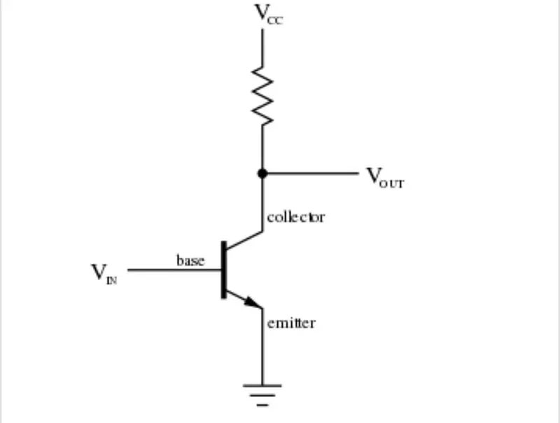
A transistor is a semiconductor device used to amplify or switch electronic signals and electrical power.It is composed of semiconductor material usually with at least three terminals for connection to an external circuit.A voltage or current applied to one pair of the transistor's terminals control the current through another pair of terminals.Because the controlled (output) power can be higher than the controlling (input) power,a transistor can amplify a signal.
Power signal acts across Collector-Emitter (CE) When there is a control signal across Base-Emitter(BE).
Bipolar Junction Transistor (BJT):
A Bipolar Junction Transistor (BJT) is a type of transistor that uses both electrons and holes and charge carriers.Unipolar transistors,such as field-effect transistors,use only one kind of charge carrier. A bipolar transistor allows a small current injected at one of its terminals to control a much larger current flowing between two other terminals, making the device capable of amplification or switching.
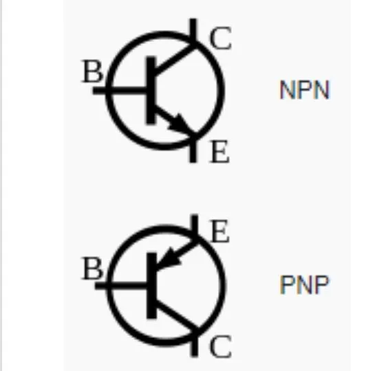
BJTs use two junctions betweeen two semiconductor types,. n-type and p-type,which are regions in a single crystal of material. The junctions can made in several different ways, such as changing the doping of the semiconductor material as it is grown,by depositing metal pellets to form alloy junctions,or by such methods as diffusion of n-type and p-type doping substances into the crystal.
The collector-emitter current can be viewed as being controlled by the base-emitter current(current control), or by the base- emitter voltage (voltage control). These views are related by the current-voltage relation of the base- emitter junction,which is the usual exponential; current-voltage curve of a p-n junction.
MOSFET (Metal Oxide Semiconductor Field Effect Transistor):
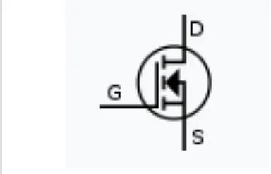
The MOSFET is a type of insulated-gate-field-effect transistor that is fabricated by the controlled oxidation of a semiconductor,typically silicon.The voltage of the covered gate determines the electrical conductivity of the device,this abiliyty to change conductivity with the amount of applied voltagecan be used for amplifying or switching electronic signals.
IGBT (Insulated Gate Bipolar Transistor):
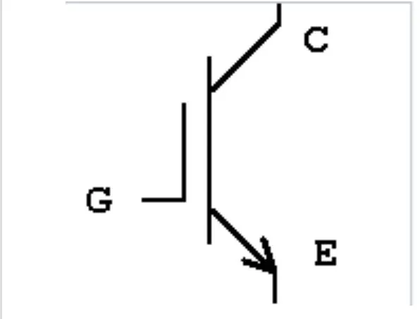
An IGBT is a three-terminal power semiconductor device primarly used as an electronic switch which,as it was developed,came to combine high efficiency and fast switching.It5 consists of of four alternating layers (P-N-P-N) that are controlled by a metal-oxide-semiconductor(MOS) gate structure with out regenerative action.Although the structure of the IGBT is topologically the same as a thyristor with a 'MOS' gate (MOS gate thyristor), the thyristor action is completely supressed and only the transistor action is permitted in the entire device operation range.It is used in switching power supplies in high-power applications:Variable-frequency drives(VFDs),electric cars,trains,variable speed refrigerators,lamp ballasts,arc-welding machines,and air conditioners.
1. To run the MATLAB demo scripr "Speed Control of DC Motor using BJT H-Breide" & evaluate the model such that armature current doesn't shoot-up when the Motor changes its direction of rotation.
Power_H-Bridge:
This example shows the simulation of an H-bridge used to generate a chopped voltage & to control the speed of a Dc motor.
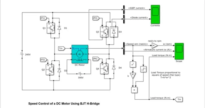
The bipolar Junction Transistor when used for power switching applications,operatres as an IGBT.When it is conducting (BJT operating in a saturation region),a forward votage Vf is developed between Collector & Emitter(in the range of 1V). Therefore the IGBT block can be used to model the BJT device.
The IGBT block does not simulate the gate current controlling the BJT or IGBT.The switch is controlled by a simulink signal (1/0).The DC motor uses the preset model (5 HP 24V 1750 rpm).It simulates a fan tyupe load(where load torque is propotional to square of speed).The armature mean voltage can be varied from 0 to 240 V when the duty cycle (specified in the pulse generator block) is varied from 0 to 100%.
The H-bridge consists of four BJT/Diode pairs (BJT simulated by IGBT models). Two transistors are switched simultaneously :Q1 and Q4 or Q2 and Q3. When Q1 & Q4 are fired ,a positive voltage is applied to the motor and diodes D2-D3 operate as free-wheeling diodes when Q1 & Q4 are switched off.When Q2 & Q3 are fired,a negative voltage is applied to the motor and diodes D1-D4 operate as free-wheeling diodes when Q2 & Q3 are switched off.
Motor & Simulation Specs:
- Power = 5 HP
- Rated Volatge = 240 V
- Rated Speed = 1750 RPM
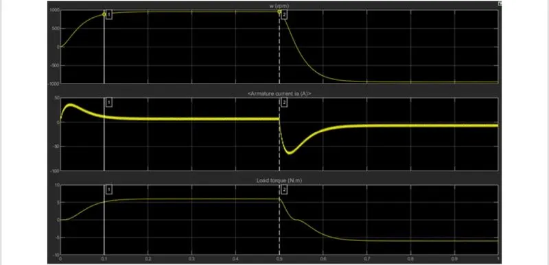
- The motor starts in the positive direction with a duty cycle of 75%
- a.DC voltage of 180V
- At t = 0.5 sec, the armature volatge is suddenly reversed and the motor runs in the negative direction.
PLOTS:
Discussion:
- Plot 1 from above figure shows the Motor Speed aganist time.
- Speed is proportional to the applied load torque.
- Plot 2 shows the Armature current drawn at each instant.
- Initial spike of current is observed in the armature (1st shoot up).
- Plot 3 from the above figure shows the load Torque aganist time.
- Torque of 6 Nm is applied to the motor initially and at time t = 0.5s,direction of rotation is reversed and a negative torque of same magnitude can be observed.
In motor,armature current (I) is given by:-
I = (V-E)/R
Where, V is the voltage supplied,E is the back emf and r is the armature Resistance.
Thus,I depends upon E and R when V is kept constant.
When the motor starts its speed remains zero i,e.E is also remains zero (Since back emf is ∝ speed of the armature).
Thus,initial starting armature current:-
I = (V-0)/R = V/R.(as E = 0).
Since, armature resistance of a motor is very small,generally less than one ohm,therefore the starting current would be very large.
As the motor speed increases,the back emf increases and the difference (V-E) goes on decreasing.this results in the gradual decrease of armature current until the motor attains its stable rated speed.Under this condition the armature current reaches its desired rated value.
- Another shoot-up can be observed in the armature current when motor changes direction from forward to reverse.
In order to aviod this,Duty ratio can be optimized.
Duty Ratio changed from 75% to 45%.
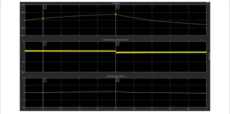
- By reducing the Duty ratio,armature current shoot-up can be completely optimized.
- But there will be considerable fall in the Load Torque and hence the Speed.
- No Load Torque of the motor has been reduced from 6 Nm to 2 Nm.
- No Load Speed is reduced from 900 RPM to 400 RPM.
- Conclusion:
- Reducing the Duty Ratio of the power modules,ultimately reduces the effect of shooting Armature current but reduces the supply voltage in the motors and result in the results in the reduction of the Rated Speed and Torque of the Motor.
2. Comparison of 4-Quadrant Chopper DC Drive(DC7) block with BJT H-Bridge Model.
Answer:
The four-Quadrant chopper DC Drive (DC7) block represents a four-quadrant,DC-supplied,chopper (or DC-DC PWM converters) drive for DC motors.This drive features closed-loop speed control with four-quiadrant operation.The speed control loop outputs the reference armature armature current of the machine.Using a PI current controller,the chopper duty cycle corrresponding to the commanded armature currentis der5ived.This duty cycle is then compared with a sawtooth carrier signal to obtain the required PWM signals for the chopper.
The main advantage of this drive,compared with other Dc drives,is that it can operate in all four quadrants (forward motering,reverse regeneration,reverse motoring & forward regeneration).In addition,due to the use of high switching frequency DC-DC converters,a lower armature current ripple(compared with thyristor-based DC drives) is obtained.However,four switching devices are required,which increases the complexity of the drive system.
DC7_Example
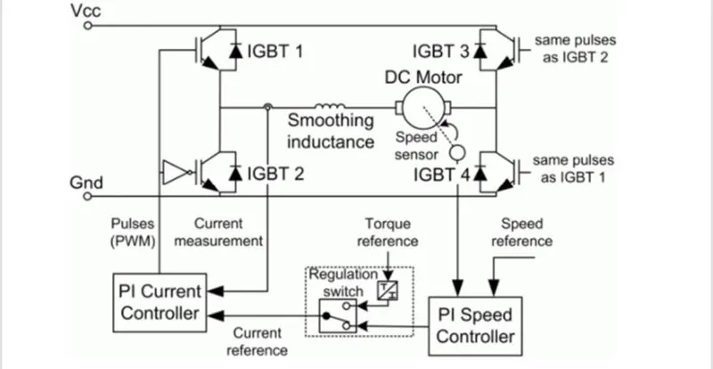
The armature voltage is provided by an IGBT Converter controlled by two PI regulators.The converter is fed by a 515 V DC bus obtained by rectification of a 380 V AC 50 Hz voltage source.In order to limit the DC bus voltage during dynamic braking mode,a braking chopper has been added between the diode rectifier and the DC7 block.
The first regulator is a speed regulator,followed by a current regulator.The speed regulator outputs the armature current reference (in P.U) used by the current controller in order to obtain the electromagnetic torque needed to reach the desired speed.The speed reference change rate follows acceleration & deceleration ramps in order to avoid sudden reference changes that could cause armature-over current and desetabilize the system.The current regulator controls the armature current by computing the appropriate duty ratios of the 5 kHz pulses of the four IGBT devices 1 & 4 are opposite to those of IGBT devices 2 & 3.This generates the average armature voltage needed to obtain the desired armature current.In order to limit the the amplitude of the current oscillations,a smoothing inductance is placed in series with the armature circuit.
Comparison with H-Bridge Model:
The machine is seperatly excited with a constant DC field voltage source.There is thus no field voltage control.By default,the field current is set to its steady-state value when a simulation is started.
The armature voltage is provided by an IGBT converter controlled by two PI regulators.The converter is fed by a constant voltage DC source.Armature current oscillations are reducing by a smoothinmg inductance connected in series with the armature circuit.
The model is descrete.Good simulation results have been obtained with a 1-μs time step.In order to simulate a digital controller device,the control system has two different sampling times:
- The speed controller sampling time.
- The current controller sampling time.
The speed controller sampling time has to be a multiple of the current sampling time.The later smapling time has to be multiple of the current sampling time has to be a multiple of the simulation time step.
The DC7 is capable of operating in all 4 quadrants `of Motoring operations.They are forward Braking,forward Motoring,Reverse Motoring and Reverse Braking.A motor operates in two modes - motoring and braking.A motor drive capable of operating in both directions of rotation and of producing both motoring and regeneration is called a four quadrant variable speed drive.
In motoring mode,the machine works as a motor and converts electrical energy into mechanical energy,supporting its motion.In braking mode,the machine works as a generator, and convertes mechanical energy into electrical energyu and as a result,it opposes its motion.The motor can work in both,forward and reverse directions i,e. in motoring and braking operationn.
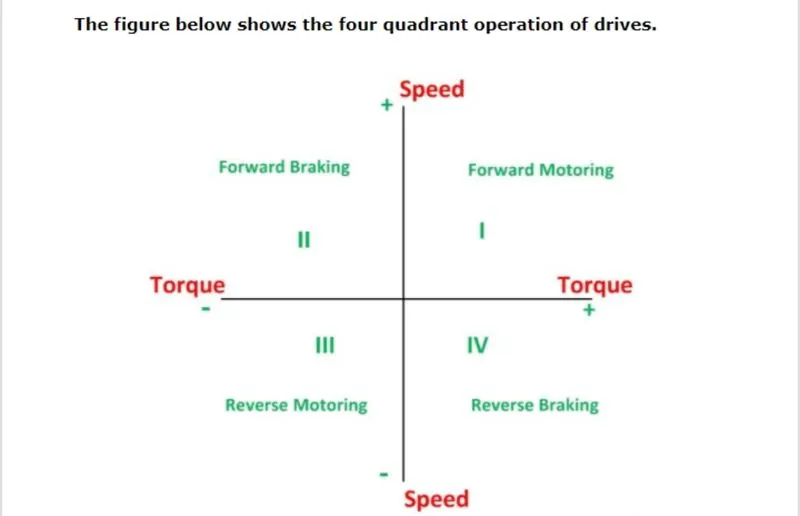
In the 1st Quadrant power developed is positive and the machine is working as a motor supplying mechanical energy.the 1st Quadrant operation is called forward Motoring. 2nd quadrant operation is known as braking.In this quadrant the direction of rotation is positive,thus the torque is negative, and thus the machine operates as a generator developing a negative torque,which opposes the motion.
The kinetic energy of the rotating parts is available as electrical energy which may be supplied back to the mains.In dynamic braking dissipates the energy is dissipated in the resistance.The 3rd quadrant operation is known a sreverse motoring.The motor works in the reverse direction.both the speed and the torque have negative values while the power is positive.In the 4th quadrant,the torque is polsitive & the speed is negative.This quadrant corresponds to braking in the reverse motoring mode.
Simulation plots with 200 HP DC Drive: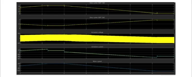
2.Develop a 2-Quadrant chopper using simulink & explain the working of the same with the relevant results.
Type C chopper or two Quadrant class C chopper:
Class-C or Type C chopper is a category of chopper which can operate in first as well as second quadrant.This basically means that,the power can either flow from source to load or load to source in this chopper.This kind of chopper is also known as Two quadrant Class-C chopper.
Operationb or working of Class-C or type-C chopper:
As,we know that,a class-A and class-B chopper operates in first and 2nd quadrant respectively.Therefore,if we connect both these types of chopper in parallel then it is possible to have chopper operation in first as well as 2nd quadrant.In fact class-c chopper is obtained by the parallel connection of class-A and clas-B chopper.Figure below shows the circuit diagram of class-c chopper.
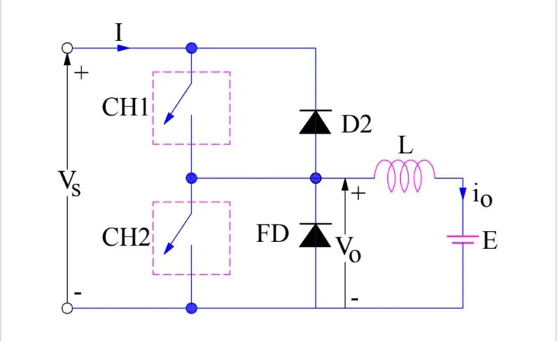
We can notice that chopper CH1,Free-wheeling diode(FD) and load are forming class-A chopper whereas chopper CH2,D2 and load are forming class-B chopper.Both these choppers are connected in parallel.To obtain first quadrant operation we should switch ON chopper CH1 and for getting second quadrant operation we should switch ON chopper CH2.Let us discuss this in detail.
Case 1: When CH1 is switched ON/OFF:
When chopper CH1 is switched ON,source Vs directly gets connected to the load and hence load voltage Vo is equal to source voltage. The direction of load current is from source to loadas shown in the circuit diagram which is assumed positive.
When CH1 is switched OFF,the free-wheeling diode FD comes into the circuit as it gets forward biased and hence shorts the load.Therefore,the output voltage Vo becomes zero.However the Io contineous to die down through the FD and L in the same direction as shown in the circuit diagram.Thus,the average output voltage Vo and current Io are positive and hence operation of chopper is in the first quadrant.
Case 2:when CH2 is switched ON/OFF :
When chopper CH2 is switched ON,load DC source E drives current through CH2 and load.The direction of this current io will be oppodite to that shown in circuit duagramand hence is assumed as negative.Output voltage Vo is zero during this time.When CH2 is made OFF,diode D2 gets forward biased and hence the current into the source from the load.The output voltage is Vs in this time as the load is connected to the source through D2 during OFF time of chopper CH2.Thus,thew load current is always negative i.e,operation of chopper is within 2nd quadrant.
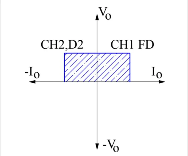
The average load voltage is always positive but the average load current may be positive or negative.Therefore,power flow may be from source to load (first Quadrant operation) or load to source(2nd Quadrant operation).The operating region of class-C chopper is shown below by the hatched area.
Caution:
Choppers CH1 and CH2 should not be ON simultaneously as this would lead to direct short circuit on the supply lines.
Application:-
Class-C choppers are used for motoring and regenerative braking of DC motors.
Realixation using Simulink:
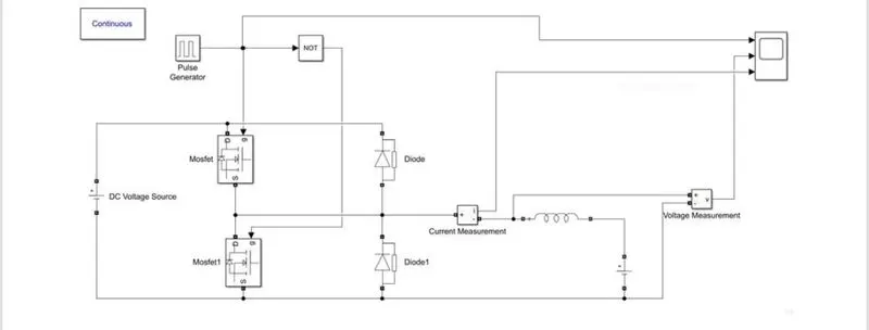
Hence,the simulink model corresponding to the circuit diagram is built using basic simulink blocks.The pulse generator is used with the NOT gate to prevent misfiring of the MOSFETs so that they do not conduct at the same time which results in the short circuit.
Pulse Generator Parameters :
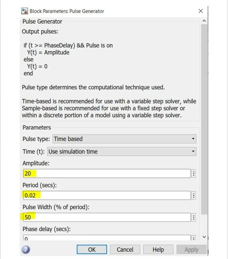
An amplitude of 20 is choosen ,so that we could see the pulses clesrly.
DC Voltage source parameters:
Source side: 24V
Load side : 12V.
Simulink OUtput: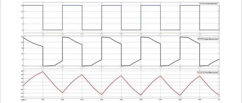
Hence,we could see clesrly that the voltage is always positive but the current becomes both positive and negative.Hence,the type-C chopper is simulated and verified.
Q No.3) Explain in a brief about operation of BLDC motor.
Brushless DC electric motors also known as electronically commutated motors(ECMs,EC motors).Primary efficiency is most important feature of BLDC motors.Because trhe rotor is the sole bearer of the magnets and it doesn't require any power,i.e,no connection,no commutator & no brushes.In place of these,the motor employs control circuitry.To detect where the rotor is at certain times,BLDC motor employ along with controllers,rotary encodersor a hall sensors.
Construction:
In this motor,the peramnent magnets attachto the rotor.The current-carrying conductors or armature windings are located on the stator.They use electrical commutation to convert electrical energy into mechanical energy.The main design difference between a brushed and brushless motor is the replacement of mechanical commutators with an electric switch circuit.A BLDC motor is a type of synchronous motor in the sense that the magnet field generated by the stator and the rotor revolveat the same frequency.
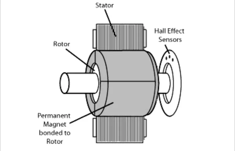
Brushless motor does not have any current carrying commutators.The field inside the brushless motor is switced through an amplifier which is trigerred by the commutating device like an optical encoder.
Working:
BLDC motor works on the principle similar to that of brushed DC motor.The Lorentz force law which states that whenever a current carrying conductor placed in a magnetic field it experiences a force.As a sequence of reaction force,and opposite force.In BLDC motor,the current carrying conductor is stationary and the permanent magnet is moving.
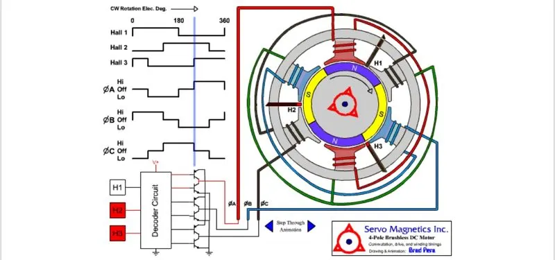
When the stator coil get a supply from source,it becomes electromagnet and stsrts producing the uniform field in the airgap.though the source of supply is DC,switching makes to generate an AC voltage waveform with trapezoidal shape.Due to the force of interaction between electromagnet stator and permanent magnet rotor,the rotor contineous to rotate.
With the switching of windings as high and low signals,corresponding winding energised as north and south poles.The permanent magnet rotor with north and south ploes align with stator poles which causes the motor to rotate.